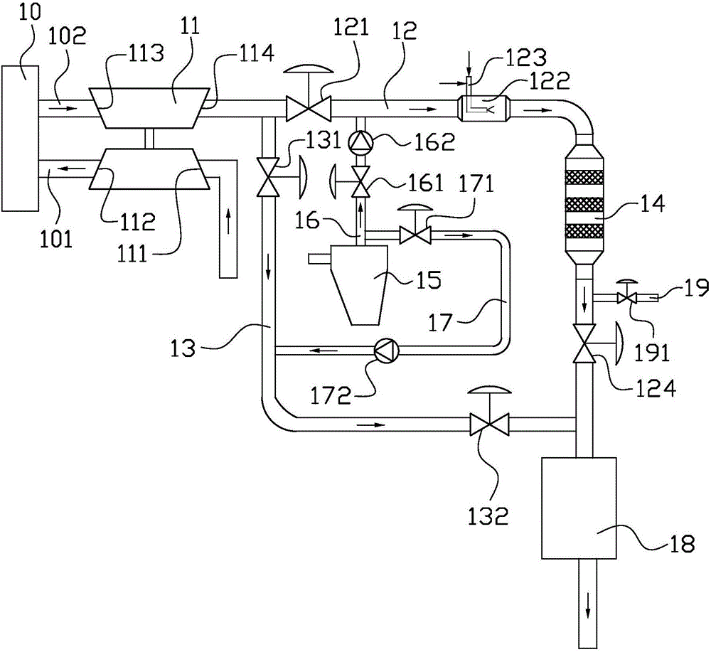
Ship exhaust gas denitration system

An exhaust gas and denitration technology, applied in the field of ship exhaust gas denitration system, can solve the problems of increasing energy consumption and cost, exhaust gas polluting the atmosphere, heat loss, etc., to achieve the effect of improving energy utilization efficiency and reducing atmospheric pollution

Active Publication Date: 2016-09-21
SUNRUI MARINE ENVIRONMENT ENG
View PDF6 Cites 6 Cited by
  • Summary
  • Abstract
  • Description
  • Claims
  • Application Information

AI Technical Summary

Problems solved by technology

However, the use of burners requires new equipment, and at the same time fuel consumption is large, increasing energy consumption and cost
[0004] On the other hand, waste oil, sludge, plastic, cardboard, cans, food waste and other garbage on board need to be disposed of by increasing incinerator inci

Method used


Image

  • Ship exhaust gas denitration system

Examples


Embodiment 1

[0047] For a 72000DWT bulk carrier, the main engine power is 8000kw, and the exhaust gas flow rate is 50000kg / h. The temperature of the diesel engine exhaust gas passing through the turbocharger is 235°C. Using the ship exhaust gas denitrification system of the present invention, the temperature can reach 345°C after being mixed with the exhaust gas from the incinerator, which can meet the temperature required for the SCR reaction. At the same time, compared with using a burner for heating, the fuel consumption (Marine Diesel MDO) is saved by about 20kg / h.

Embodiment 2

[0049] For a 150,000DWT crude oil tanker, the main engine power is 15,000kw, the exhaust gas flow rate is about 130,000kg / h, and the exhaust gas temperature of the diesel engine passing through the turbocharger is 225°C. Using the ship exhaust gas denitrification system of the present invention, the temperature can reach 340°C after being mixed with the exhaust gas from the incinerator. °C, which can meet the temperature required by the SCR reaction. At the same time, compared with using a burner for heating, the fuel saving (Marine Diesel MDO) consumption is about 37.5kg / h.

Embodiment 3

[0051] For a 2000TEU container ship, the main engine power is 17000kw, the exhaust gas flow rate is 150000kg / h, and the exhaust gas temperature of the diesel engine passing through the turbocharger is 230°C. Using the ship exhaust gas denitrification system of the present invention, the temperature can reach 340°C after being mixed with the exhaust gas from the incinerator , which can meet the temperature required for SCR reaction. At the same time, compared with using a burner for heating, the fuel saving (Marine Diesel MDO) consumption is about 41kg / h.


PUM


Abstract

The invention provides a ship exhaust gas denitration system. The ship exhaust gas denitration system comprises an exhaust gas denitration pipeline, an exhaust gas bypass pipeline, a denitration reactor, a heating pipeline and a heating bypass pipeline, wherein the exhaust gas denitration pipeline is connected with an exhausting end of a diesel engine through a first valve; the exhaust gas bypass pipeline is connected with the exhausting end of the diesel engine through a second valve; the denitration reactor is connected into the exhaust gas denitration pipeline; the heating pipeline is connected with an incinerator through a third valve; the heating bypass pipeline is connected with the incinerator through a fourth valve; when the first valve and the third valve are opened and the second valve and the fourth valve are closed, exhaust gas of the incinerator and exhaust gas of the diesel engine are mixed in the exhaust gas denitration pipeline and the temperature of the exhaust gas is adjusted; then the exhaust gas enters the denitration reactor to be denitrated; when the first valve and the third valve are closed and the second valve and the fourth valve are opened, the exhaust gas of the incinerator and the exhaust gas of the diesel engine are exhausted by the heating bypass pipeline and the exhaust gas bypass pipeline respectively. The heating pipeline is connected with the incinerator and the exhaust gas denitration pipeline and heating and temperature regulation are carried out by utilizing temperature difference of the exhaust gas of the incinerator and the exhaust gas of the diesel engine, so that the temperature of the mixed exhaust gas meets reaction requirements of the reactors.

Description

technical field [0001] The invention relates to the field of atmospheric environment protection, in particular to a ship exhaust gas denitrification system. Background technique [0002] According to the requirements of the amendments to the Regulations for the Prevention of Air Pollution from Ships in Annex VI of the MARPOL 73 / 78 Convention adopted by the International Maritime Organization (IMO), the nitrogen oxides in the exhaust gas of ships must be treated to meet the standards before they can be discharged. For low-speed marine diesel engines (speed n<130rpm), the nitrogen oxide content after treatment should be less than 3.4g / kwh, but for current low-speed diesel engines, this emission requirement cannot be met only by optimizing the combustion method of diesel engines. Therefore, marine diesel engines must be equipped with marine exhaust gas denitrification systems, and Selective Catalytic Reduction (SCR) technology is currently the most applicable diesel engine p...

Claims


Application Information

Patent Timeline
IPC IPC(8): B01D53/90B01D53/86B01D53/56B01D53/96
CPCB01D53/8631B01D53/90B01D53/96B01D2259/4566
Inventor 高健范昊张文涛于航刘光洲
Owner SUNRUI MARINE ENVIRONMENT ENG
Why Eureka
Try Eureka