View screen self-guiding type machined part burr removing machine

A deburring and self-guided technology, which is applied in the direction of machine tools, metal processing equipment, and workpiece feed movement control suitable for grinding workpiece edges, and can solve the problem of affecting the size of parts, losing luster on the surface of parts, and increasing processing costs, etc. To solve the problem, achieve the effect of high surface machining accuracy, shortening the cutting time, and precise and controllable movement

Inactive Publication Date: 2016-09-21
UNIV OF SHANGHAI FOR SCI & TECH
View PDF7 Cites 7 Cited by
  • Summary
  • Abstract
  • Description
  • Claims
  • Application Information

AI Technical Summary

Problems solved by technology

One is to use the method of manual deburring, which is labor-intensive, low in efficiency, and easy to cause damage to parts
The second is to use the chemical deburring method, but this method is complicated to operate and is not conducive to assembly line operations
The third is electrolytic deburring, using electrolysis to remove burrs on metal parts, but it will make the surface of the parts lose their original luster and even affect the size of the parts
The fourth is ultrasonic deburring, which uses the instantaneous impact force of hundreds of atmospheres to remove burrs, but it cannot remove burrs that can be seen with the naked eye and have high bonding strength.
Fifth, high-pressure water jet deburring, using water as the medium, uses the instantaneous impact force of water to remove burrs, and the equipment cost is high, which will increase the processing cost
In addition, none of the above deburring methods can only perform deburring operations on the burred parts of the workpiece to achieve automation, high efficiency, and high-quality production goals.

Method used


Image

  • View screen self-guiding type machined part burr removing machine
  • View screen self-guiding type machined part burr removing machine
  • View screen self-guiding type machined part burr removing machine

Examples


Embodiment Construction

[0017] The present invention will be further described below in conjunction with the accompanying drawings and embodiments.

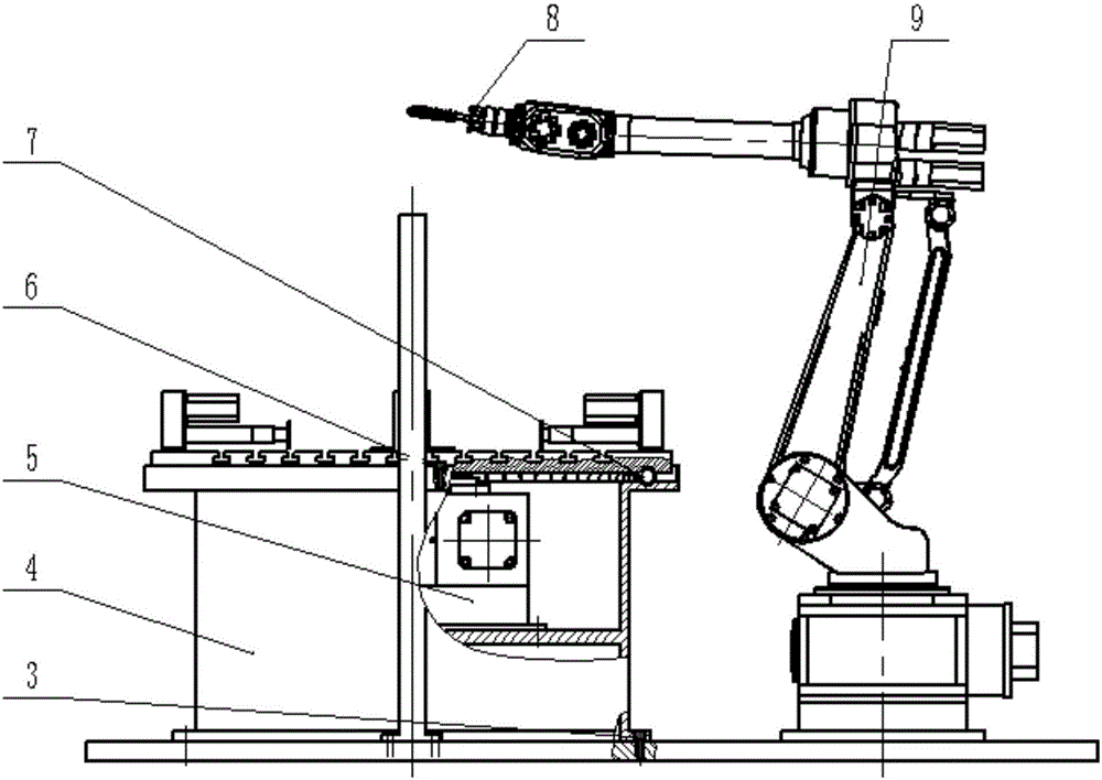
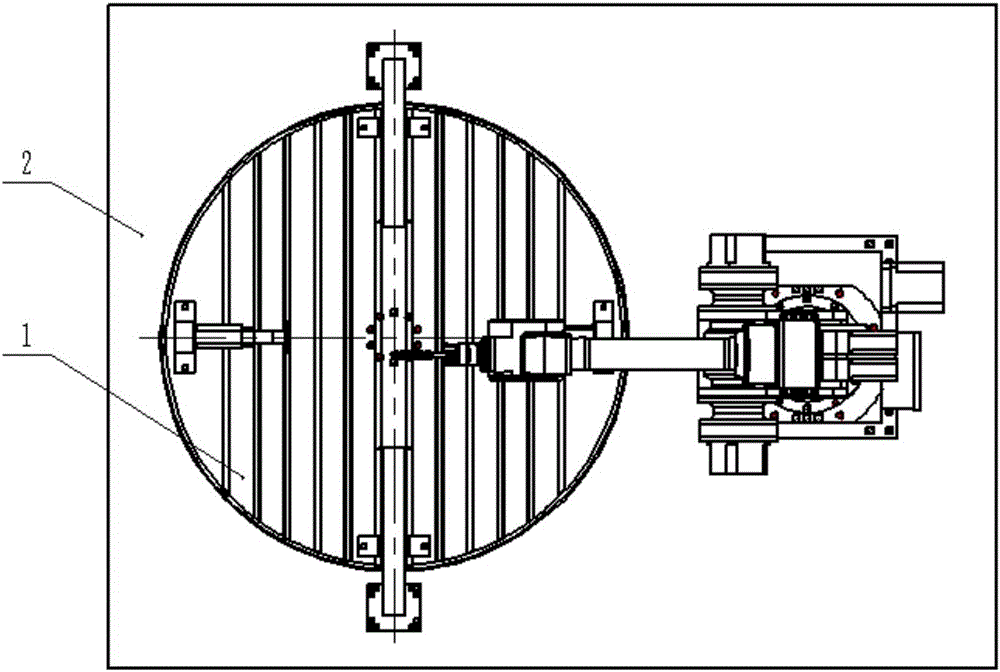
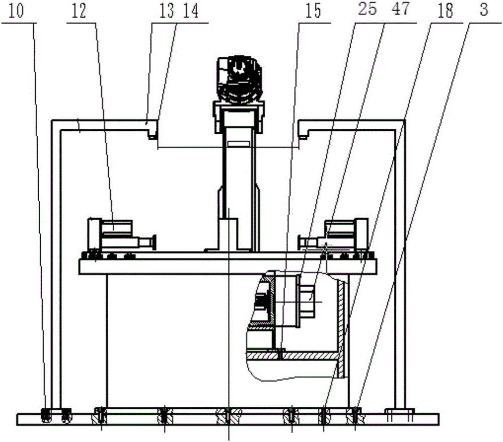
[0018] see Figure 1-6 , The video screen self-guided workpiece deburring machine of the present invention consists of a base 4, a rotating part 5, a sensor assembly 6, a workbench assembly, a magnetic needle cutter assembly, and mechanical arms 9 and other mechanisms. The base 4 is fixed on the ground 2 with bolts 3, and is used to carry rotating parts, workbench components and parts, etc. The base 4 is fixedly connected to the rotating part 5 by screws 15 . The mechanical arm 9 is fixed on the ground 2, and the magnetic needle cutter assembly is housed on the mechanical arm 9.

[0019] The rotary part 5 also includes a small electric box cover 25, a small electric box 26, a worm motor flange 27, a deep groove ball bearing 28, a flat key 29, a worm screw 30, a worm screw bearing flange 33, a rotary base 34, a retaining ring 35, Deep groove ball bear...


PUM


Abstract

The invention relates to a view screen self-guiding type machined part burr removing machine. A rotation component is fixedly connected in a base. A magnetic needle cutter assembly is installed on a mechanical arm. The upper end and the lower end of a spindle are installed in a rotation base through a bearing and a blind flange correspondingly. A worm gear is connected to the spindle and connected with a worm in a meshing mode. One end of the worm is fixedly connected with an output shaft of a rotary motor. The other end of the worm is connected with the rotation base through a bearing and a blind flange. The rotary motor is fixed to the side face of the rotation base. The upper end of the spindle is fixedly connected with a workbench assembly. A sensor support rod is fixed to the ground. A visual sensor is embedded into the upper end of the sensor support rod. According to the view screen self-guiding type machined part burr removing machine, through the visual sensor, a machined part can be scanned and a burr position of the part can be detected, comparison with a three-dimensional model is made through system software, a cutting path of a burr cutter is generated automatically, the mechanical arm conducts burr removing operation through the burr removing cutter according to the cutting path, and thus intelligent, efficient and mechanized burr removing operation is achieved on a workpiece.

Description

technical field [0001] The invention relates to a machine for removing burrs from workpieces, in particular to a machine for removing burrs from workpieces with video screen self-guidance. Background technique [0002] At present, there are many schemes for removing burrs from workpieces. One is to use the method of manual deburring, which is labor-intensive, inefficient, and easy to cause damage to parts. The second is to utilize the chemical deburring method, but this method is complicated to operate and is not conducive to assembly line operation. The third is electrolytic deburring, using electrolysis to remove burrs on metal parts, but it will make the surface of the parts lose their original luster and even affect the size of the parts. The fourth is ultrasonic deburring, which uses the instantaneous impact force of hundreds of atmospheres to remove burrs, but it cannot remove burrs that can be seen with the naked eye and have high bonding strength. Fifth, high-pres...

Claims


Application Information

Patent Timeline
Patent Type & Authority Applications(China)
IPC IPC(8): B24B9/06B24B49/00B24B41/00B24B47/00B24D7/18
CPCB24B9/06B24B41/00B24B47/00B24B49/00B24D7/18
Inventor 林献坤刘涛戴凤强
Owner UNIV OF SHANGHAI FOR SCI & TECH
Why Eureka
Try Eureka