
Online testing device and method for residual strength modulation of Y-waveguide modulator

A technology of waveguide modulator and residual strength, which is applied in the direction of measuring devices, instruments, surveying and navigation, etc., can solve the problems of low efficiency, slow measurement speed, manual testing, etc., and achieve the effect of high measurement accuracy, high speed and complete functions

Inactive Publication Date: 2016-09-21
BEIHANG UNIV
View PDF6 Cites 9 Cited by
  • Summary
  • Abstract
  • Description
  • Claims
  • Application Information

AI Technical Summary

Problems solved by technology

[0005] At present, in the existing methods for measuring the residual intensity modulation of Y-waveguide modulators, although direct measurement with an oscilloscope can measure the magnitude of the residual intensity modulation intuitively, manual testing is required, and the measurement speed is slow, the efficiency is low, and it is not convenient and fast. Analyzing the error sources of residual intensity modulation
The method of phase-locked amplification and demodulation to obtain residual intensity modulation can only amplify the specified frequency component. If the modulation signal uses a sawtooth wave, other frequency components except the reference signal frequency will not be amplified. Therefore, this measurement method only Suitable for situations where the modulating signal is a sine wave
Another method is to use the method of spectrum analysis to collect the signal through the analog-to-digital converter, and then convert the time-domain signal to the frequency domain for spectrum analysis. This method can only perform quantitative calculations on each frequency component, and cannot intuitively Analyzing the Mechanism of Residual Intensity Modulation

Method used


Image

  • Online testing device and method for residual strength modulation of Y-waveguide modulator
  • Online testing device and method for residual strength modulation of Y-waveguide modulator
  • Online testing device and method for residual strength modulation of Y-waveguide modulator

Examples


Embodiment Construction

[0026] The present invention will be further described in detail below in conjunction with accompanying drawings and examples.

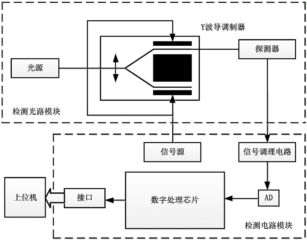
[0027] Such as figure 1 As shown, an on-line test device for residual intensity modulation of a Y waveguide modulator includes a detection optical circuit module, a detection circuit module and a host computer.

[0028] Y waveguide modulator residual intensity modulation online test device and its online measurement method are to collect the residual intensity modulation digital signal after analog-to-digital conversion in real time through the digital processing chip, and send it to the host computer through serial port communication after being processed in the digital processing chip, and finally The magnitude and waveform of the residual intensity modulation signal are displayed on the host computer interface.

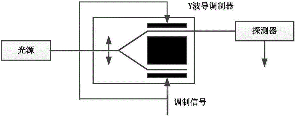
[0029] Such as figure 2 As shown, the detection optical path module includes a light source, a Y waveguide modulator, and a detector....


PUM


Abstract

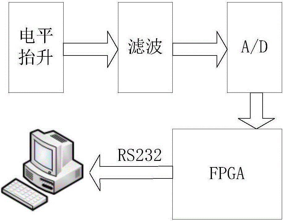
The invention discloses an online testing device and method for residual strength modulation of a Y-waveguide modulator. The online testing device comprises a detecting optical path module, a detecting circuit module and a host computer. The working principle of the device is that a light source sends an optical signal to the Y-waveguide modulator, one end of an output branch of the Y-waveguide modulator is connected to a detector, and the optical signal is subjected to photovoltaic conversion through the detector, then passes through the level elevation circuit, a filter circuit and a high-speed A / D conversion chip, is processed by an FPGA (field-programmable gate array) and is finally sent to the host computer through an RS232 serial port for display. With design of the online testing device for residual strength modulation of the Y-waveguide modulator, the absolute magnitude of residual strength modulation can be obtained directly and rapidly, the problems of low precision and low testing speed are solved, one objective real-time online method is provided, and compared with the conventional methods adopting an oscilloscope, a lock-in amplifier, spectral analysis and the like, the testing precision is higher, the speed is higher and the functions are more complete.

Description

technical field [0001] The invention belongs to the field of performance testing of integrated optical devices, and specifically refers to an FPGA-based on-line testing device for rapidly testing residual intensity modulation of a Y-waveguide modulator and an on-line measurement method thereof. Background technique [0002] Fiber optic gyroscope is an all-solid-state pure optical inertial device, the basic principle is Sagnac effect and optical reciprocity. The optical path of the fiber optic gyro is mainly composed of optical devices, polarization-maintaining fiber rings and detectors. Among them, the optical device includes a broadband light source, a fiber coupler and a Y waveguide modulator; the Y waveguide modulator integrates a beam splitter, a polarizer and a broadband phase modulator, and plays the role of light splitting / combining, polarizing / analyzing and optical phase modulation Its function is an important part of the optical path. [0003] Usually, in the fibe...

Claims


Application Information

Patent Timeline
IPC IPC(8): G01C25/00G01C19/72
CPCG01C19/721G01C25/00G01C25/005
Inventor 杨德伟赵艳郑月姚天龙翁苍杰
Owner BEIHANG UNIV
Learn More