
System architecture of all-liquid crystal automobile instrument

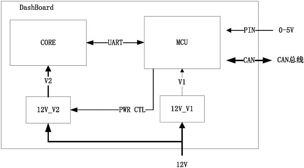
A technology of automotive instrumentation and system architecture, applied in the field of automotive instrumentation, can solve problems such as poor reusability, difficulty in platform replacement, and unsightly instrument development interface, and achieve the effects of speeding up the development cycle, saving development costs and development time

Inactive Publication Date: 2016-09-21
ZHEJIANG ZHONGKE AUTOROCK AUTOMOBILE ELECTRONICS
View PDF5 Cites 2 Cited by
  • Summary
  • Abstract
  • Description
  • Claims
  • Application Information

AI Technical Summary

Problems solved by technology

However, there are two technical problems in the existing automotive instruments: 1. Poor reusability and difficult platform replacement
2. The instrument development interface is not beautiful enough
Therefore, as one of the main components of human-computer interaction, the existing automotive instrumentation solution can no longer meet the requirements of high performance and rapid development

Method used


Image

  • System architecture of all-liquid crystal automobile instrument
  • System architecture of all-liquid crystal automobile instrument
  • System architecture of all-liquid crystal automobile instrument

Examples


Embodiment 1

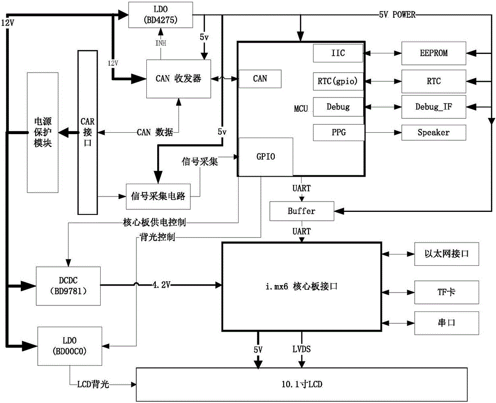
[0024] like figure 2 As shown, in the system architecture of the full LCD car instrument in this embodiment, the core processor adopts IMX6, the power supply voltage adopts 4.2V, the controller adopts Fujitsu MB91F522, and the power supply voltage is 5V. The power chip 12V_V1 is BD4275 and 12V_V2 is BD9781.

[0025] IMAX6 is equipped with Ethernet interface, TF card, serial port, and is connected with 10.1-inch LCD screen.

[0026] The whole system adopts 12V power supply, 12V voltage is converted to 5V voltage through LDO (low dropout regulator) low dropout linear regulator, and 5V power supply is used for CAN transceiver, MCU, EEPROM, RTC clock, debug interface, buffer, and signal acquisition circuit powered. The 12V voltage is converted into 4.2V voltage by DC-DC (direct current to direct current conversion) to supply power for IMX6. The 12V voltage passes through the LDO (Low Dropout Linear Regulator) to provide backlight power for the 10.1-inch LCD screen, and the pow...

Embodiment 2

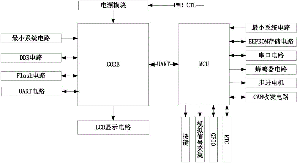
[0031] like image 3 As shown, it is a system block diagram of a combination car instrument, which uses a 7-inch LCD and a stepper motor. The MCU adopts Fujitsu MB96F385, and the CORE adopts Fujitsu MB86R01 (maximum support 1024*768 resolution). The serial port is used for communication between MCU and CORE. The MCU peripheral circuit mainly includes the minimum system circuit (including crystal oscillator circuit, reset circuit, download / debugging circuit), EEPROM circuit (saving mileage, fault code and customer configuration information), serial port circuit (for debugging output and communicating with CORE), Buzzer circuit, stepper motor (for vehicle speed indication), CAN transceiver circuit, RTC (real time clock), GPIO, analog signal acquisition (AD acquisition), buttons (for interface switching, mileage reset), etc. CORE peripheral circuits mainly include the minimum system circuit, DDR circuit, FLASH circuit, UART circuit and LCD display circuit. The power control of...


PUM


Abstract

The invention discloses a system architecture of an all-liquid crystal automobile instrument, comprising a core processor CORE, a micro control unit MCU, a first voltage regulation chip, and a second voltage regulation chip. The micro control unit MCU is connected with a power supply through the first voltage regulation chip, and the core processor CORE is connected with the power supply through the second voltage regulation chip. The micro control unit MCU is connected with the second voltage regulation chip. The micro control unit MCU and the core processor CORE carry out serial communication. The micro control unit MCU receives a level signal, a voltage signal and a CAN signal of an automobile body. Through the technical scheme, signal acquisition and interface presenting software can be developed separately, the two sides do not depend on each other on the basis that the communication protocol is determined, and the product development cycle is speeded up.

Description

technical field [0001] The invention belongs to the technical field of automobile instruments, and in particular relates to a system architecture of a full liquid crystal automobile instrument. Background technique [0002] The current automobile instruments include purely mechanical instruments and some mechanical instruments with liquid crystal display. The purely mechanical automobile instruments use mechanical pointers to display information. Mechanical instruments with partial liquid crystal displays use mechanical pointers and LEDs as information presentation methods, which are more superior than mechanical instruments. However, the current mechanical instrument with liquid crystal display has a small liquid crystal display area, and usually a single controller (8-bit or 16-bit single-chip microcomputer) can complete the entire functional requirement. However, with the diversified needs of customers, the popularity of electric vehicles, and some smart applications, th...

Claims


Application Information

Patent Timeline
IPC IPC(8): G05B19/042
CPCG05B19/0423G05B2219/21106
Inventor 黄海涛叶源彭寿星王成刘鹏金星
Owner ZHEJIANG ZHONGKE AUTOROCK AUTOMOBILE ELECTRONICS
Learn More