Compression structure for compression forming machine

A technology of compression mechanism and forming machine, which is applied in the direction of material forming presses, presses, stamping machines, etc., can solve the problems of waste of resources, easy blockage, a large number of by-products, etc., to achieve convenient processing and manufacturing, increase input power, The effect of improving compression efficiency

Active Publication Date: 2016-09-28
NANJING AGRI MECHANIZATION INST MIN OF AGRI
View PDF6 Cites 1 Cited by
  • Summary
  • Abstract
  • Description
  • Claims
  • Application Information

AI Technical Summary

Problems solved by technology

Due to the backward production and processing methods, a large number of by-products will be produced in the harvesting, transportation, and processing links of the fruit and vegetable crop industry chain, and they cannot be effectively used, resulting in serious waste of resources, economic losses, and environmental pollution.
According to the special survey on the comprehensive utilization of agricultural product production and processing by-products carried out by the Agricultural Products Processing Bureau of the Ministry of Agriculture in 2014, the number of agricultural product production and processing by-products in my country is increasing year by year. The comprehensive utilization rate is less than 5%, and most of the fruit and vegetable residues are thrown away as garbage
Because the screw extrusion type is mostly used for the processing of expandable agricultural materials, it is not suitable for the molding of materials with high fiber content; the structure of the grinding roller compression molding equipment is complicated, and the processing and manufacturing are difficult, and the material straw is easy to be blocked when it is extruded, and it is not easy to block after being blocked. Cleaning, when cleaning, the upper mold needs to be disassembled, and then the middle module is cleaned, which is time-consuming and laborious; secondly, the ring mode straw briquetting machine mainly relies on the rotating pressure wheel to squeeze the straw out of the die hole, and when the pressure wheel rotates , due to the existence of materials, it will generate a lot of force on the modules around the die hole, which consumes a lot of power, has low efficiency, and the die life is short and the maintenance cost is high

Method used


Image

  • Compression structure for compression forming machine
  • Compression structure for compression forming machine
  • Compression structure for compression forming machine

Examples


specific Embodiment approach

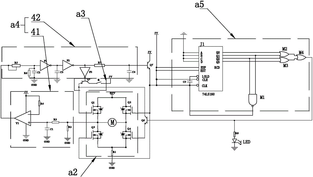
[0035] As an improved specific implementation, the detection circuit a4 includes:

[0036] The current detection unit 41 is coupled to the external motor to detect and output the current flowing through the external motor;

[0037] The delay judgment unit 42 is coupled to the current detection unit 41, and is also coupled to the base of the switch transistor Q7, to receive the motor current signal output by the current detection unit 41, and compare it with the threshold value set in it, if the motor current is greater than threshold, then send a signal to the switch transistor Q7, the switch transistor Q7 conducts the 5V power supply and the control terminal of the IGBT tube Q2 and the control terminal of the IGBT tube Q3. By setting the current detection unit 41, the current flowing through the motor can be effectively detected, and by setting the delay judgment unit 42, the motor current detected by the current detection unit 41 can be delayed and judged. The function of t...


PUM


Abstract

The invention discloses a compression structure for a compression forming machine. The compression structure comprises a rack, a controller, a main motor, a reducing mechanism and a compression mechanism. The main motor is fixedly mounted on one side of the rack. The reducing mechanism is fixedly mounted on the rack and fixedly connected with the main motor. The compression mechanism is fixedly mounted on the side, back to the reducing mechanism, of the rack and fixedly connected with the reducing mechanism. The compression structure is characterized in that the reducing mechanism comprises a driving gear, a driven gear and a connecting rod mechanism; the compression mechanism comprises a compression sleeve, a compression die and a compression sliding block; and the compression die comprises a feeding part and a forming part, and a feeding opening is formed in the top of the compression sleeve. According to the compression structure for the compression forming machine, the connecting rod mechanism drives the compression sliding block to conduct compression forming on garden stuff residues, the period of storage of the garden stuff residues can be prolonged, the storage space is saved, long-distance transportation is facilitated, and good conditions are created for following deep machining such as active constituent extraction and feedstuff utilization.

Description

technical field [0001] The invention relates to a compression structure of a compression molding machine, in particular to a compression structure of a compression molding machine used for compressing fruit and vegetable peels. Background technique [0002] my country is a major producer of fruit and vegetable products. The planting area and output of fruits and vegetables rank first in the world, and it is the second largest crop group after food crops. Due to the backward production and processing methods, a large number of by-products will be produced in the harvesting, transportation, and processing links of the fruit and vegetable crop industry chain, and they will not be effectively used, resulting in serious resource waste, economic losses, and environmental pollution. According to the special survey on the comprehensive utilization of agricultural product production and processing by-products carried out by the Agricultural Products Processing Bureau of the Ministry ...

Claims


Application Information

Patent Timeline
Patent Type & Authority Applications(China)
IPC IPC(8): B30B1/14B30B11/04H02K7/116H02K7/06H02P29/028H02P29/032H02H7/085
CPCH02H7/0858H02K7/06H02K7/116H02P29/027H02P29/032B30B1/14B30B11/04
Inventor 田昆鹏张彬李显旺王锦国黄继承沈成周杨王帅
Owner NANJING AGRI MECHANIZATION INST MIN OF AGRI
Why Eureka
Try Eureka