Relay protection device and system, realizing plug-and-play, of transformer station

A relay protection device and protection device technology, applied in the field of smart substations, can solve the problems that operation and maintenance personnel are difficult to meet the application requirements of new communication technologies, the level of network communication technology is weak, and there are relatively high risks in safe operation, so as to ensure real-time reliability It is convenient to transfer, check and rectify, and avoid the effect of network storm

Active Publication Date: 2016-09-28
STATE GRID SHANDONG ELECTRIC POWER +2
View PDF4 Cites 11 Cited by
  • Summary
  • Abstract
  • Description
  • Claims
  • Application Information

AI Technical Summary

Problems solved by technology

[0004] One is to use optical fiber to transmit information between the process layer and the interval layer. The length of the optical fiber is long and it is prone to failure;
[0005] The second is to increase the merging unit and intelligent terminal equipment at the process layer to realize the conversion of photoelectric signals, the collection of voltage, current and switch state information, and the transmission of opening and closing signals. The merging unit (MU) and the intelligent terminal (ST) Equipment products are of poor quality and often break down;
[0006] The third is that the information transmission between the process layer and the interval layer depends on the network, and the existing technical level of the operation and maintenance personnel is difficult to meet the

Method used


Image

  • Relay protection device and system, realizing plug-and-play, of transformer station
  • Relay protection device and system, realizing plug-and-play, of transformer station
  • Relay protection device and system, realizing plug-and-play, of transformer station

Examples


Example Embodiment

[0044] The present invention will be further described below in conjunction with the drawings and embodiments.

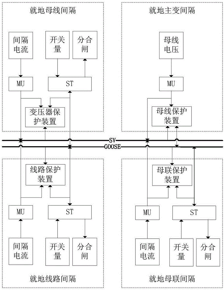
[0045] Such as figure 1 As shown, in the traditional protection system configuration scheme, each bay protection device is installed on site. In the protection interval of the line, transformer and bus tie, each interval MU collects the CT current of the primary equipment of the interval, and collects signals such as the state of the interval switch through the ST; in the bus protection interval, the PT voltage is connected to the merging unit of the interval; The merging unit of the transformer, bus tie and busbar interval establishes an SV switching network through the switch, which is used to transmit three-phase voltage and current AC information; the intelligent terminal of the line, transformer and bus tie interval establishes the GOOSE switching network through the switch for transmission DC information such as switching value.

[0046] Line, transformer, and bus...


PUM


Abstract

The invention discloses relay protection device and system, realizing plug-and-play, of a transformer station. The protection device comprises a line protector, a transformer protector, a bus connection protector and a bus separation protector relying on one another and associated with one another; required current and switching amount information are connected to the line protector, the transformer protector and the bus connection protector directly via secondary cables; opening/closing control is output directly via the secondary cables, and the protectors directly act on a switching mechanism of a bay level; the bus voltage collected by a voltage transformer is connected to the bus separator protector in the analog form; and the bus separator protector is directly connected to the line protector, the transformer protector and the bus connection protector via two optical cables in a point-to-point manner. On the premise that faults of the electric network can be overcome rapidly, the relay protection device system of the invention can further reduce the operation risk of the electrical network as well as the labor intensity of maintenance staff, and it is ensured that the electrical network operates safely, reliably and stably.

Description

technical field [0001] The invention relates to the technical field of intelligent substations, in particular to a substation relay protection device and system for realizing plug-and-play. Background technique [0002] Conventional stations have high reliability, mature technology, and stable operation, but there are problems such as complex circuits, poor versatility of protection devices and secondary circuits, high technical requirements, difficult rectification and countermeasures, and heavy operation and maintenance workload. For this reason, smart grids emerged as the times require . The smart grid uses a high-speed network communication platform as the basis for information transmission, and automatically completes functions such as information collection, measurement, control, protection, measurement, and detection. Smart substations have three key features. One is to realize the conversion between analog electrical signals and digital optical signals by adding pro...

Claims


Application Information

Patent Timeline
IPC IPC(8): H02H7/22
CPCH02H7/226
Inventor 李乃永吴金玉王林王思城李明明晋飞林勇马献丽孙继磊唐敏宗传帅
Owner STATE GRID SHANDONG ELECTRIC POWER
Why Eureka
Try Eureka