Optical sensing device for heart rate and blood pressure monitor

An optical sensor and monitor technology, applied in cardiac catheterization, vascular evaluation, etc., can solve the problems of poor reliability, low detection sensitivity, weak signal strength, etc., and achieve the effect of good reliability, high sensitivity, and strong signal

Active Publication Date: 2016-10-05
MIKOLTA OPTICAL TECH CO
View PDF9 Cites 7 Cited by
  • Summary
  • Abstract
  • Description
  • Claims
  • Application Information

AI Technical Summary

Problems solved by technology

Such a sensor structure has several problems: 1. Because the light-emitting angle of the light-emitting device is relatively large, especially the smaller patch-type light emitters generally have a Lambertian distribution with a beam angle of 120 degrees, which only has a small A small part of the light will hit the desired detection position and be reflected by the blood vessel before being received by the light receiver
Most of the light is wasted where it is not needed, so the resulting signal strength is relatively weak
2. Due to the relatively large light-emitting angle of the light-em

Method used


Image

  • Optical sensing device for heart rate and blood pressure monitor
  • Optical sensing device for heart rate and blood pressure monitor
  • Optical sensing device for heart rate and blood pressure monitor

Examples


Embodiment 1

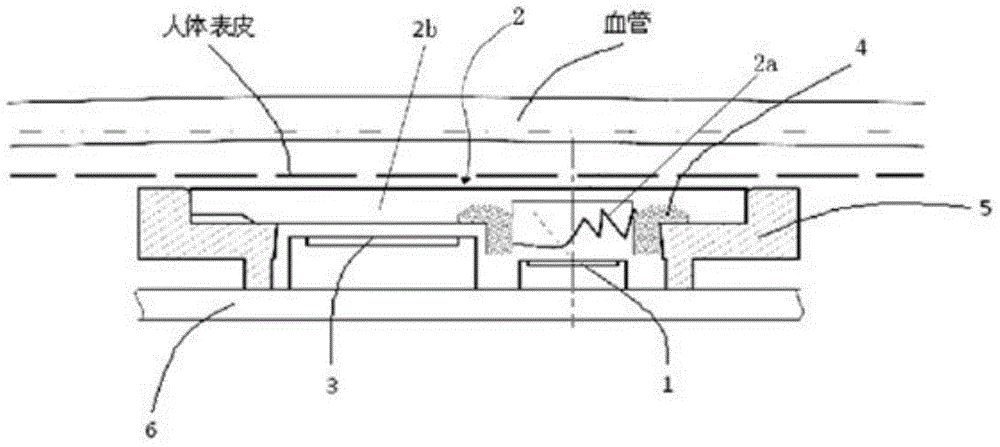
[0051] This embodiment discloses an optical sensing device for a heart rate and blood pressure monitor, and the cross-sectional view of its specific implementation is as follows image 3 shown. From image 3 As can be seen in the figure, the optical sensing device consists of a light-emitting device 1 (in various embodiments of the present invention, the light-emitting device 1 can use an LED light-emitting diode or a laser emitting tube), an optical lens 2, a photoelectric receiving tube 3, a light-shielding black frame 4, and a housing 5 , and PCB (printed circuit board) 6 components. Wherein, the optical lens 2 includes a light-gathering window 2 a and a light-transmitting window 2 b, the light-gathering window 2 a is located above the light emitting device 1 , and the light-transmitting window 2 b is located above the photoelectric receiving tube 3 .

[0052] Wherein, the three-dimensional view of the optical lens 2 is shown in FIG. 4 . Figure 4A-Figure 4E As shown, th...

Embodiment 2

[0063] This embodiment discloses an optical sensing device for a heart rate and pressure monitor. The cross-sectional view of the second embodiment is basically similar to that of the first embodiment, specifically as in the first embodiment image 3 shown. The design principle is also the same, specifically as in Embodiment 1 Figure 5 shown. The only difference is that the light-gathering window 2a of the optical lens 2 is an oblique Fresnel lens that rotates around the axis OP. This embodiment 2 discloses an optical sensing device for a heart rate and pressure monitor consisting of a light emitting device 1, an optical lens 2, a photoelectric receiving tube 3, a light-shielding black frame 4, a housing 5, and a PCB (printed circuit board) 6 composition. Described optical lens 2 comprises condensing window 2a and light-transmitting window 2b, and its 3-dimensional view is as Figure 9A-9E shown. Its three-dimensional model perspective view (housing 5 is hidden) such as ...

Embodiment 3

[0065] This embodiment discloses an optical sensing device for a heart rate and pressure monitor. The design principle of its specific implementation is as follows: Figure 11 As shown, it is composed of a light-emitting device 1 , an optical lens 2 , a photoelectric receiving tube 3 , a light-shielding black frame 4 , a housing 5 , and a PCB (printed circuit board) 6 . The optical lens 2 includes a light-gathering window 2a and a light-transmitting window 2b.

[0066] From Figure 11 It can be seen from the figure that the concentrating window 2a is a ruled Fresnel structure lens, and the side of the concentrating window 2a close to the light-emitting device 1 is an inclined plane; the side away from the light-emitting device 1 is an inclined Fresnel surface. It includes at least one transmission surface and one or more tooth-shaped total reflection surfaces. The material of the light-gathering window 2a is transparent optical PMMA resin. The function of the light-gatherin...


PUM


Abstract

The invention discloses an optical sensing device for a heart rate and blood pressure monitor, comprising a light-emitting device, an optical lens, a photoelectric receiving tube and a light-shielding black frame, wherein the optical lens includes a light-gathering window above the light-emitting device and a photoelectric The light-transmitting window above the receiving tube; the light-shielding black frame is located above the light-emitting device and is set between the light-gathering window and the light-transmitting window; the light-gathering window adopts a Fresnel structure, which includes at least one transmission surface and one or more teeth composition of reflective surfaces. Due to the use of the oblique-axis Fresnel lens, it can achieve the purpose of concentrating and turning the light path with a relatively thin thickness. It concentrates the LED light and converges it to the measured point on the skin in an oblique direction, passing through the measured point. After being reflected by the blood vessels in the measuring point, it is received by the photoelectric receiving tube through the transparent window, thereby generating pulse and blood signals. The optical sensing device has the characteristics of strong signal, low noise, high sensitivity, accuracy, good reliability and the like.

Description

technical field [0001] The invention relates to the technical field of optical sensing devices, in particular to an optical sensing device used in heart rate and blood pressure monitors. Background technique [0002] With the increasing pressure of modern urban life, smoking and alcohol, overeating, obesity, insomnia, anxiety and other problems, the pressure on people's heart is also increasing, and the human heart rate carries a lot of information about the health status of the heart and body , Arrhythmia is facing a younger trend, if you do not pay attention to your own health, the consequences will be disastrous. The so-called arrhythmia refers to changes in the normal sequence of pulses that cause the heart to pump blood between the body. Since abnormal heart rhythms may only occur sporadically, it often takes long-term continuous monitoring to detect abnormal heart rhythms. Fast, accurate and smart heart rate and blood pressure monitors are necessary. [0003] The pat...

Claims


Application Information

Patent Timeline
IPC IPC(8): A61B5/021
Inventor 郎欢标
Owner MIKOLTA OPTICAL TECH CO
Why Eureka
Try Eureka