Light emitting diode lamp 3-dimentional phase transition heat dissipation method and device

A technology of light-emitting diodes and heat sinks, which is applied in the direction of lighting devices, cooling/heating devices of lighting devices, light sources, etc., to achieve the effects of reducing system thermal resistance, reducing the complexity of production processes, and reducing product costs

Inactive Publication Date: 2016-10-05
蒋琰
View PDF4 Cites 4 Cited by
  • Summary
  • Abstract
  • Description
  • Claims
  • Application Information

AI Technical Summary

Problems solved by technology

[0007] In view of the above problems, the present invention provides a 3-dimensional phase change heat dissipation method and device for light-emitting diode lamps to solve the heat dissipation problem of high-power LED lamps

Method used


Image

  • Light emitting diode lamp 3-dimentional phase transition heat dissipation method and device
  • Light emitting diode lamp 3-dimentional phase transition heat dissipation method and device
  • Light emitting diode lamp 3-dimentional phase transition heat dissipation method and device

Examples


Embodiment 1

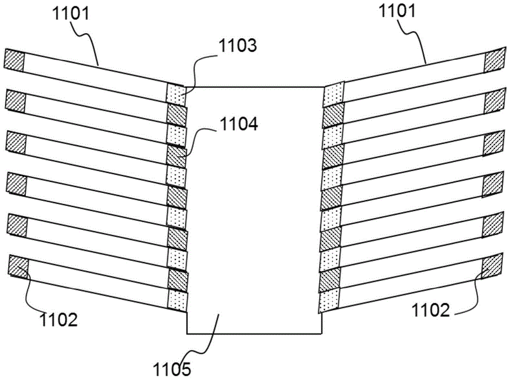
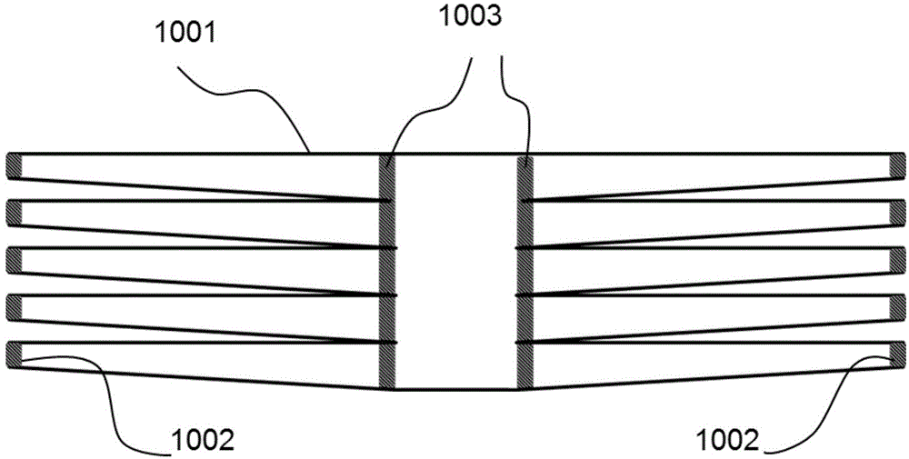
[0058] Embodiment 1 of the 3-dimensional phase change heat dissipation method and device for light-emitting diode lamps provided by the present invention is as follows: figure 1 As shown, the multi-layer fin structure constitutes a condenser 105 , which is sequentially connected with a liquid storage tank 104 of a storage liquid-gas phase change working medium 103 and an evaporator 102 to form an airtight hollow cavity 110 .

[0059] Each fin structure in the condenser 105 is composed of two ring-shaped high thermal conductivity material sheets. The high thermal conductivity material can be copper, aluminum or high thermal conductivity plastic. The thickness of the hollow space between the ring-shaped high thermal conductivity material sheets is about 1-20mm. The plane where each fin structure is located is parallel to the surface of the evaporator.

[0060] The liquid-gas phase change material can be selected from water or alcohol, and is stored in the liquid storage tank 104...

Embodiment 2

[0066] Embodiment 2 of the 3-dimensional phase change heat dissipation method and device for light-emitting diode lamps provided by the present invention is as follows: Figure 4 As shown, when the actual working environment temperature is higher than the expected working temperature of LED lamps, this structure can be adopted. and figure 1 The structure of the shown embodiment 1 is similar. The multi-layer fin structure constitutes a condenser 405, which is sequentially connected with the liquid storage tank 404 of the reserve liquid-gas phase change working medium 403 and the evaporator 402 with the LED chip 401 packaged on the outer surface, forming airtightness. The hollow cavity 410, together with the transparent mask 411, the LED chip driving circuit 406, and the electrical connection structure 407 constitute the second embodiment of the 3-dimensional phase change heat dissipation method and device for light-emitting diode lamps.

[0067]The difference between this embo...

Embodiment 3

[0069] Embodiment 3 of the 3-dimensional phase change heat dissipation method and device for light-emitting diode lamps provided by the present invention is as follows: Figure 5 shown. and figure 1 The structure of the shown embodiment 1 is similar, and the multi-layer fin structure constitutes a condenser 505, which is sequentially connected with the liquid storage tank 504 of the reserve liquid-gas phase change working medium 503 and the evaporator 502 with the LED chip 501 packaged on the outer surface, forming airtightness The hollow cavity 510, together with the transparent mask 511, the LED chip driving circuit 506, and the electrical connection structure 507 constitute Embodiment 3 of the 3-dimensional phase change heat dissipation method and device for light-emitting diode lamps.

[0070] The difference between this embodiment and Embodiment 1 is that the plane where each fin structure is located is perpendicular to the surface of the evaporator. The upper part of t...


PUM


Abstract

The invention provides a light emitting diode lamp 3-dimentional phase transition heat dissipation method and device. The 3-dimentional phase transition heat dissipation method is characterized in that hollow fin structures and a phase transition heat transfer technique are coupled, and heat matching between a high-power electronic device heat power and natural air convection heat transfer power through 3-dimentional heat transfer of a phase transition working medium in a vacuum cavity. A condenser formed by a plurality of hollow fin structures is a special part of the method. The 3-dimentional phase transition heat dissipation device includes an evaporator, the condenser, a liquid storage groove and a phase transition working medium, the structure of the 3-dimentional phase transition heat dissipation device can be flexible designed according to an application environment, and the 3-dimentional phase transition heat dissipation device has wide applicability. The 3-dimentional phase transition heat dissipation device is large in heat dissipation power, has no power consumption, is light in weight, is simple in manufacturing technique, is low in cost, and can solve the heat management problem of light emitting diode lamp fundamentally.

Description

technical field [0001] The invention relates to the field of thermal management of high-power electronic devices, in particular to a three-dimensional phase-change heat dissipation method and a device thereof applied to light emitting diode (Light Emitting Diode, LED) lamps. Background technique [0002] LED light sources have broad application prospects in many fields such as communications and lighting, and are considered to be important lighting sources in the future. At present, more than 60% of the input energy in the LED light source is finally converted into heat energy. If the heat generated inside the lamp cannot be exchanged to the external environment space in time through an effective heat dissipation mechanism, it will lead to a decrease in the LED optical power and a shift in the peak wavelength of light emission. , life-span rapid attenuation and other serious problems. With the continuous improvement of the power of LED lamps, their heat dissipation problem ...

Claims


Application Information

Patent Timeline
Patent Type & Authority Applications(China)
IPC IPC(8): F21V29/00F21Y101/02
Inventor 蒋琰
Owner 蒋琰
Why Eureka
Try Eureka