
Multiple-effect hot air seed drying device

A technology of drying device and hot air device, which is applied in the direction of drying gas arrangement, drying solid materials, local agitation dryer, etc., can solve the problems of affecting seed germination rate, high energy consumption, high labor intensity, etc., so as to avoid poor drying effect Good, reduce operating cost, use safe and reliable effect

Inactive Publication Date: 2016-10-05
哈尔滨尼亚农业有限公司
View PDF3 Cites 1 Cited by
  • Summary
  • Abstract
  • Description
  • Claims
  • Application Information

AI Technical Summary

Problems solved by technology

[0003] In the prior art, the commonly used seed drying method is a combination of ventilated drying and natural drying, which has the advantages of simplicity, energy saving, economical safety, Its disadvantage is that it is easy to be restricted by weather and site conditions, the labor intensity is relatively high, it requires more manpower, and the cost is high
Secondly, for the drying of large batches of seeds, drying or drying equipment is mostly used at present, while traditional drying equipment has more or less shortcomings in drying seeds, such as long drying cycle, uneven drying color, Energy consumption is high, drying quality cannot be guaranteed, and seed germination rate is affected, etc.

Method used


Image

  • Multiple-effect hot air seed drying device

Examples


Embodiment 1

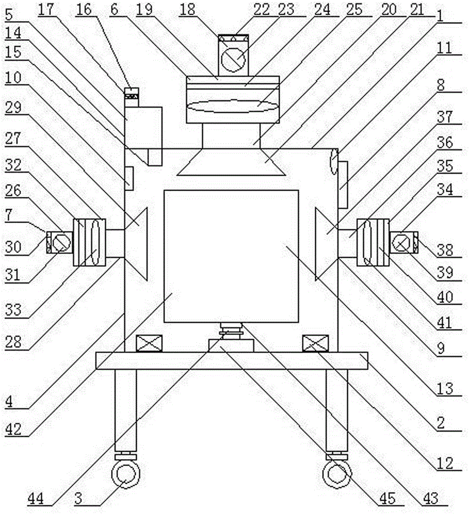
[0017] As shown in the figure, a multi-effect hot air seed drying device includes a fuselage 1, a frame 2 is installed at the lower end of the fuselage 1, casters 3 are installed at the bottom end of the frame 2, and a drying box is installed at the upper end of the frame 2 4. The dehumidifying device 5 is installed on the left side of the top of the drying box 4, the first hot air device 6 is installed in the middle of the top of the drying box 4, the second hot air device 7 is installed on the left side of the drying box 4, and the drying box 4. A controller 8 is installed at the upper end of the right side, a third hot air device 9 is installed at the middle end of the right side of the drying box 4, a temperature sensor 10 is installed at the upper left side of the inside of the drying box 4, and a humidity sensor 10 is installed at the upper right end of the inside of the drying box 4. A sensor 11, a circulation fan 12 is installed on the left and right sides of the inne...

Embodiment 2

[0019] As shown in the figure, the dehumidifier 5 is composed of a dehumidifier 14, an air suction pipe 15, and an exhaust pipe 16. The air suction pipe 15 is installed at the bottom of the dehumidifier 14, and the air suction pipe 15 is installed at On the left side of the top of the drying box 4, an exhaust pipe 16 is installed on the left side of the top of the dehumidifier 14, and an activated carbon filter screen 17 is installed inside the exhaust pipe 16.

Embodiment 3

[0021] As shown in the figure, the first hot air device 6 is composed of a first air suction pipe 18, a first hot air chamber 19, a first air inlet pipe 20 and a first air inlet duct 21. The top end of the first hot air chamber 19 is Install the first suction pipe 18, the bottom end of the first hot air chamber 19 is connected to the first air inlet duct 21 through the first air inlet pipe 20, and the first air inlet duct 21 is installed in the middle of the top inside the drying box 4 The first filter panel 22 is installed at the mouth of the first suction pipe 18, the first suction fan 23 is installed inside the first suction pipe 18, and the first ultraviolet extinguisher is installed at the upper end of the first hot air chamber 19. Bacteria lamp tube 24, the first heat exchanger 25 is installed at the lower end of the first ultraviolet sterilizing lamp tube 24.


PUM


Abstract

A multiple-effect hot air seed drying device comprises a machine body. A rack is arranged at the lower end of the machine body. Foot wheels are arranged at the bottom end of the rack. A drying box is arranged at the upper end of the rack. A dehumidification device is arranged at the left side of the top end of the drying box. A first hot air device is arranged in the middle of the top end of the drying box. A second hot air device is arranged at the middle end of the left side of the drying box. A controller is arranged at the upper end of the right side of the drying box. A third hot air device is arranged at the middle end of the right side of the drying box. A temperature sensor is arranged at the upper end of the left side in the drying box. A humidity sensor is arranged at the upper end of the right side in the drying box. Each of the left side and the right side of the bottom end in the drying box is provided with a circulating fan. A rotary screen is arranged at the middle end in the drying box. According to the multi-effect hot air seed drying device, the multi-effect hot air design is adopted, multi-side hot air drying is achieved, the seed drying efficiency is improved greatly, and the seed drying uniformity is improved greatly.

Description

technical field [0001] The invention relates to a seed drying device, in particular to a multi-effect hot air seed drying device. Background technique [0002] Generally, newly harvested seeds have a water content of 25%-45%. The seeds at this time are not suitable for storage, and the following hazards are likely to occur during storage: First, the respiration of high-moisture seeds is relatively strong, which will release a lot of heat, which is easy to cause the seeds to rot. Mildew; second, some seeds will produce alcohol due to hypoxic respiration, which will poison the seeds and reduce seed activity; third, when high-moisture seeds encounter low temperatures, they are prone to freezing, reducing seed activity, and even causing seed death; Fourth, high-moisture seeds tend to germinate when the temperature reaches a certain level, making the seeds unusable; fifth, high-moisture seeds are also prone to breeding insects and endangering seed safety. Therefore, before th...

Claims


Application Information

Patent Timeline
IPC IPC(8): F26B9/06F26B21/00F26B25/00
CPCF26B9/063F26B21/004F26B25/00
Inventor 肖海波孙红瑞吴国会
Owner 哈尔滨尼亚农业有限公司
Learn More