Eureka AIR delivers breakthrough ideas for toughest innovation challenges, trusted by R&D personnel around the world.

Sludge layer filtering and settling pond and method thereof

A sludge layer and sedimentation tank technology, applied in the field of sludge layer filtration sedimentation tank, can solve the problems of large area of ​​sedimentation tank, large horizontal area of ​​sedimentation tank, complex structure of filter tank, etc. Operation management, good effluent quality

Inactive Publication Date: 2016-10-12
王灿 +2
View PDF7 Cites 5 Cited by
  • Summary
  • Abstract
  • Description
  • Claims
  • Application Information

AI Technical Summary

Problems solved by technology

In order to improve the removal rate of suspended particles in the sedimentation tank and reduce the horizontal area of ​​the sedimentation tank, people have researched and developed the inclined plate sedimentation tank. Because it only relies on gravity for sedimentation, it needs The sedimentation time is too long and the horizontal area of ​​the sedimentation tank is too large, which makes the sedimentation tank occupy a large area and invest a lot
Filtration is an effective treatment process for removing tiny particles with relatively low concentrations in muddy water, but the structure of the filter tank is complex, and the filter layer of the filter tank needs to be backwashed regularly, resulting in large head loss and complicated operation and management

Method used


Image

  • Sludge layer filtering and settling pond and method thereof
  • Sludge layer filtering and settling pond and method thereof

Examples


Embodiment Construction

[0029] The present invention will be further described below in conjunction with the accompanying drawings and embodiments.

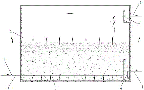
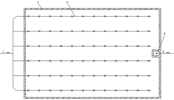
[0030] As shown in the figure, the sludge filter sedimentation tank includes a tank body 2, an inlet pipe 1, an outlet pipe 5, and a mud discharge pipe 6. A mud discharge pipe 6 and a water outlet pipe 5 are arranged on the top. Around the mud outlet of the mud discharge pipe 6, an upper opening enclosure is formed to form a sludge bucket 4. An upper opening is arranged around the water outlet of the water outlet pipe 5. The slag separation plate forms a clear water bucket 7; the water inlet pipe 1 is also connected to the water distributor 3 arranged in the pool body 2, so that the incoming water can be evenly filtered after being distributed. The water distributors 3 are several arranged in parallel; a pump 8 is also arranged on the water inlet pipe 1 to control the upstream flow rate of the muddy water to be treated.

[0031] The method for sludge l...


PUM


Abstract

The invention discloses a sludge layer filtering and settling pond and a method thereof. The sludge layer filtering and settling pond comprises a pond body, a water-in pipe, a water-out pipe, a water distributer and a sludge discharging pipe; the water-in pipe is arranged on the lower portion of the pond body, the lower portion of the other side of the pond body is provided with the sludge discharging pipe, the upper portion of the other side of the pond body is provided with the water-out pipe, the periphery of a sludge discharging opening of the sludge discharging pipe is provided with a fence with the upper portion being open, a sludge hopper is formed, the periphery of a water outlet of the water-out pipe is provided with a slag insulation plate with the upper portion being open, and a clear water hopper is formed; the water-in pipe is further connected with the water distributor arranged in the pond body. The settling speed of muddy water to be treated is higher than the upward flowing speed of the muddy water so that large-particle suspended solids can be settled at the bottom of the pond body to form a sludge filtering layer, and when the muddy water to be treated is continued to be introduced into the pond body from the water-in pipe, impurities in the muddy water to be treated are either intercepted or condensed into large particles in the process of flowing through the sludge filtering layer. The sludge layer filtering and settling pond is large in surface load, good in quality of output water and easy to operate and manage and can further remove organic pollutants dissolved in the muddy water.

Description

technical field [0001] The invention relates to a sludge layer filtering sedimentation tank and a method thereof, in particular to a processing method and equipment for removing suspended matter in muddy water, in particular to removing tiny particles in muddy water. Background technique [0002] The process by which suspended particles in water are separated from water by gravity is called sedimentation. The process of intercepting suspended particles in water with a granular filter layer such as quartz sand is called filtration. [0003] Sedimentation and filtration are currently the most widely used water treatment processes, which can effectively remove suspended impurities in water. In order to improve the removal rate of suspended particles in the sedimentation tank and reduce the horizontal area of ​​the sedimentation tank, people have researched and developed the inclined plate sedimentation tank. Because it only relies on gravity for sedimentation, it needs The se...

Claims


Application Information

Patent Timeline
IPC IPC(8): B01D21/00B01D21/02
CPCB01D21/0012B01D21/02C02F1/52
Inventor 王灿赵元超肖凡
Owner 王灿
Why Eureka
Eureka Blog
Learn More