Glass fiber bobbin transporting device and control method thereof

A technology of transportation device and glass fiber yarn, which is applied in the field of glass fiber yarn bobbin transportation device and its control, can solve the problems of high labor cost and low work efficiency, achieve low labor cost, high work efficiency, and improve speed and accuracy Effect

Active Publication Date: 2016-10-12
WUHAN TEXTILE UNIV
View PDF7 Cites 7 Cited by
  • Summary
  • Abstract
  • Description
  • Claims
  • Application Information

AI Technical Summary

Problems solved by technology

[0004] The purpose of the present invention is to overcome the defects and problems of low work efficiency and high labor cost in the prior art, and provide a glass fiber bobbin transport device with high work efficiency and low labor cost and its control method

Method used


Image

  • Glass fiber bobbin transporting device and control method thereof
  • Glass fiber bobbin transporting device and control method thereof
  • Glass fiber bobbin transporting device and control method thereof

Examples


Embodiment 1

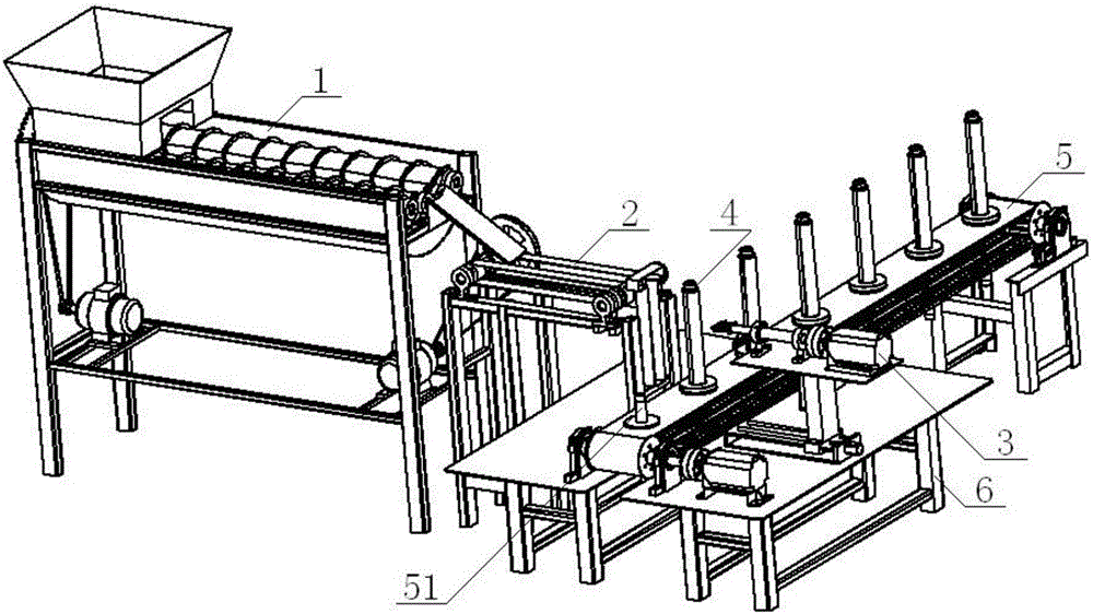
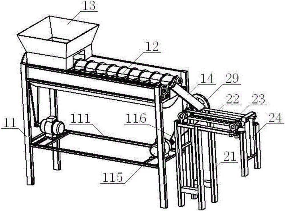
[0061] see Figure 1 to Figure 8 , a glass fiber bobbin transport device, comprising a synchronous toothed belt 5, bobbin 4, the bobbin 4 is placed on the synchronous toothed belt 5; the glass fiber bobbin transport device also includes a feeding part 1, Bobbin positioning part 2, bobbin turning part 3, described synchronous toothed belt 5 is installed on the frame 6, one side of synchronous toothed belt 5 is provided with bobbin positioning part 2, the other side of synchronous toothed belt 5 The bobbin turning part 3 is arranged on the side, and the side of the bobbin positioning part 2 away from the synchronous toothed belt 5 is provided with a feeding part 1; the feeding part 1 includes a feeding frame 11 and a pair of To the rotating roll 12, the position above the one end of the opposite rotating roll 12 on the said feeding frame 11 is equipped with a bobbin bin 13, and the position on the feeding frame 11 located at the other end of the opposing rotating roll 12 is inst...

Embodiment 2

[0064] Basic content is the same as embodiment 1, the difference is:

[0065] see Figure 1 to Figure 5 , the positioning frame 21 includes a No. 1 support 211, a No. 2 support 212, and a No. 3 support 213. The No. 1 support 211 and the No. 2 support 212 are parallel to each other, and the No. 1 support 211 is connected to the No. The No. 1 bracket 212 is connected, the No. 1 bracket 211 is perpendicular to the No. 3 bracket 213, and the No. 1 bracket 211 is connected with the No. 3 bracket 213 through the No. 1 crossbeam 215, and the No. 2 bracket 212 is mutually perpendicular to the No. 3 bracket 213. Vertical, and No. two support 212 is connected with No. three support 213 by No. two beam 216, and described No. three support 213 is installed on the frame 6; Described No. three support 213 comprises No. one vertical beam 217, No. two vertical beam 218, No. 2 longitudinal beam 219, one end of the No. 2 longitudinal beam 219 is vertically connected with the No. 1 vertical bea...

Embodiment 3

[0067] Basic content is the same as embodiment 1, the difference is:

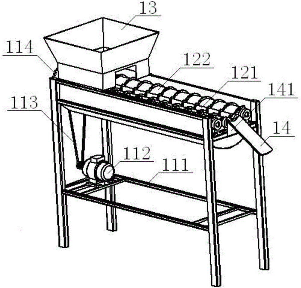
[0068] see Figure 1 to Figure 5 , the bottom of the feeding frame 11 is provided with a mounting bracket 111, and one end of the mounting bracket 111 is provided with a No. 1 motor 112, and the No. 1 motor 112 is connected with the No. 1 pulley 114 through a No. 1 belt 113. The mounting bracket The other end of 111 is provided with No. 2 motor 115; Said opposite rotating roll 12 comprises two No. 1 rotating rolls 121 that are in contact with each other, and both sides of No. 1 rotating roll 121 are provided with No. 2 rotating roll 122 that contacts with it. , the outer diameter of No. 2 rotating roll 122 is greater than the outer diameter of No. 1 rotating roll 121, and No. 1 rotating roll 121 is connected with No. 1 pulley 114; , the angle between the bobbin discharge trough 14 and the vertical plate 141 is an acute angle, the other end of the vertical plate 141 is vertically connected with the end of t...


PUM


Abstract

A glass fiber bobbin transporting device comprises a feeding component, a bobbin positioning component, a bobbin overturning component, a bobbin and a synchronous toothed belt. The bobbin positioning component and the bobbin overturning component are arranged on the two sides of the synchronous toothed belt correspondingly. The feeding component is arranged on the side, far away from the synchronous toothed belt, of the bobbin positioning component and comprises an opposite-direction rotation roller, a bobbin bin and a bobbin discharging groove. The bobbin positioning component comprises a synchronous conveying belt and a guiding frame. The bobbin overturning component comprises a clamping pneumatic claw provided with a bobbin clamping frame, an overturning shaft and an overturning motor. In the transporting process, the bobbin is conveyed into the guiding frame sequentially through the opposite-direction rotation roller, the bobbin discharging groove and the synchronous conveying belt, a bobbin body is clamped through the bobbin clamping frame, then, the overturning motor drives the overturning shaft to overturn so that the bobbin can be rotated, the bobbin body is loosened through the bobbin clamping frame, and the bobbin falls onto the synchronous toothed belt. The design is high in work efficiency and low in labor cost.

Description

technical field [0001] The invention relates to the field of textile machinery, in particular to a glass fiber bobbin conveying device and a control method thereof, which are mainly suitable for improving the working efficiency of cutting the remaining yarn of the glass fiber bobbin and reducing labor costs. Background technique [0002] Glass fiber is widely used in the fields of electrical insulation and fireproof buildings, especially in the production process of circuit board substrates, a large number of glass fiber bobbins are needed, and the number of bobbins used by large-scale production enterprises reaches 1 million a year. branch. Due to the requirements of the production process, each glass fiber bobbin needs to be replaced when there is a small amount of surplus yarn. In order to ensure the repeated use of the glass fiber bobbin, a lot of manual work is required to cut and remove the surplus yarn on the glass fiber bobbin. [0003] The Chinese patent applicatio...

Claims


Application Information

Patent Timeline
Patent Type & Authority Applications(China)
IPC IPC(8): B65G65/46B65G15/12B65G47/252B65G37/00B65G47/57
CPCB65G15/12B65G37/00B65G47/252B65G47/57B65G65/46B65G2201/0217B65G2207/14
Inventor 张成俊左小艳张弛吴晓光张远皓杨涛戴健雄
Owner WUHAN TEXTILE UNIV
Why Eureka
Try Eureka