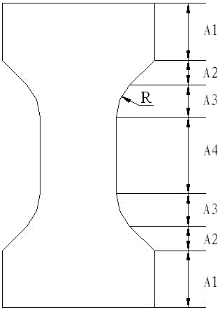
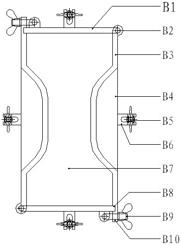
Test piece of concrete direct tensile test, test piece forming die and integrated equipment
A tensile test and complete set of device technology, which is applied in the measurement device, the preparation of the test sample, and the application of stable tension/pressure to test the strength of the material, etc. The inherent characteristics of concrete and the inability to obtain test results can achieve the effect of easy manual loading, high test efficiency, and saving manpower and material resources.
- Summary
- Abstract
- Description
- Claims
- Application Information
AI Technical Summary
Problems solved by technology
Method used
Image
Examples
Embodiment 1
[0057] The following combination Figure 1 to Figure 11 Specific embodiments of the present invention are described in detail, the concrete direct tensile test specimen, the specimen forming mold and the complete set of equipment of the present invention comprise the concrete direct tensile test specimen, the concrete direct tensile test specimen forming mold and the concrete direct tensile test specimen. Tensile test set.
[0058] Concrete direct tensile test specimens are dumbbell-shaped tensile specimens with square section and equal thickness. For concrete, a heterogeneous and discontinuous multi-phase composite material, the failure process is controlled by the internal random distribution of defects and cracks. The fracture point of the specimen under the action of axial stress is uncertain. In order to obtain more valuable information on the failure behavior of concrete, the specimen must be destroyed in the predetermined failure section. It is very important to realiz...
Embodiment 2
[0080] see Figure 1 to Figure 8 and Figures 12 to 14 . Embodiment 2 is all the same as embodiment 1 in the concrete direct tension test specimen and its forming mold, and the concrete direct tension test complete set of equipment adapted to the structure type of the specimen, and the technology of embodiment 2 is different from embodiment 1 The characteristic is that the deformation sensor adopts a resistance strain gauge type extensometer 18B, and the clamp D5 on the gauge distance column D3 of the upper frame and the corresponding clamp D5 of the lower frame are used to fix the limit rod D15, and the end of the limit rod D15 One side of the extensometer is provided with a blade slot D16 for limiting the position of the extensometer blade, and the other side is provided with an anti-slip groove D17 to prevent the clamp from falling off. The clamp can be a rubber band or a spring. During the test, the resistance strain gauge The blade of the type extensometer 18B is always...
Embodiment 3
[0082] see Figure 1 to Figure 8 . Under the condition of a universal testing machine, a set of test piece tensioning and clamping fixtures 17 can be directly connected to the upper jaw of the testing machine through the ball joint joint 16, and the other set of test piece tensioning and clamping fixtures 17 passes through first. The ball joint joint 16 links the load sensor 20, and the load sensor 20 links the lower jaw of the testing machine through the ball joint joint 16, and adjusts the position of the crossbeam of the universal testing machine so that the test piece 7 is clamped on the upper and lower sets of test piece sheets. Pull the clamping fixture 17 and make the load value zero. After connecting the data acquisition system, the loading test can be completed through the automatic loading program of the universal testing machine, and the data recording and post-processing can be completed through the acquisition system. The data acquisition system is integrated in th...
PUM
| Property | Measurement | Unit |
|---|---|---|
| Particle size | aaaaa | aaaaa |
Abstract
Description
Claims
Application Information
 - R&D
- Intellectual Property
- Life Sciences
- Materials
- Tech Scout
- Unparalleled Data Quality
- Higher Quality Content
- 60% Fewer Hallucinations
Browse by: Latest US Patents, China's latest patents, Technical Efficacy Thesaurus, Application Domain, Technology Topic, Popular Technical Reports.
© 2025 PatSnap. All rights reserved.Legal|Privacy policy|Modern Slavery Act Transparency Statement|Sitemap|About US| Contact US: help@patsnap.com


