Preparation method of high-resistance reduction corrosion-resistant and abrasion-resistant grounding body

A corrosion-resistant and wear-resistant technology, which is applied in the field of preparation of high-resistance corrosion-resistant grounding bodies, can solve problems such as damage to the electroplating layer and increase the corrosion rate of the grounding electrode, so as to achieve increased wear resistance, short preparation cycle, The effect of low equipment cost

Inactive Publication Date: 2016-10-12
ELECTRIC POWER RES INST STATE GRID JIANGXI ELECTRIC POWER CO +2
View PDF8 Cites 0 Cited by
  • Summary
  • Abstract
  • Description
  • Claims
  • Application Information

AI Technical Summary

Problems solved by technology

However, due to the thin coating of galvanized flat steel, it is very easy to damage the electroplating layer during transportation and electrode production, so that the galvanized flat steel buried in the ground takes the surface damage point as the corrosion center, and the corrosive substances promote galvanizing. The layer is gradually peeled off, which increases the corrosion rate of the ground electrode

Method used


Image

  • Preparation method of high-resistance reduction corrosion-resistant and abrasion-resistant grounding body
  • Preparation method of high-resistance reduction corrosion-resistant and abrasion-resistant grounding body

Examples


preparation example Construction

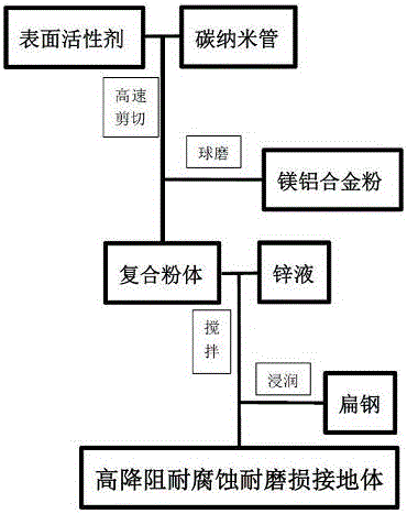
[0017] The implementation steps of a method for preparing a high-resistance, corrosion-resistant, and wear-resistant grounding body are as follows:

[0018] Step 1: subjecting the surfactant and the carbon nanotube to high-speed shearing, so that the surface of the carbon nanotube is coated with the surfactant;

[0019] Step 2: ball milling the low-melting-point magnesium-aluminum alloy powder and the carbon nanotubes obtained in step 1, so that the carbon nanotubes are embedded in the alloy powder;

[0020] Step 3: Add the composite powder after ball milling in step 2 into the molten zinc liquid, and mix evenly at a certain stirring speed;

[0021] Step 4: Immersing the flat steel into the zinc liquid in which carbon nanotubes are fused in step 3, so that the surface of the flat steel is coated with a zinc layer, and finally a high-resistance-resistance, corrosion-resistant, and wear-resistant grounding body is obtained.

[0022] The surfactant described in step 1 is any one...

Embodiment 1

[0028] (1) 10g sodium lauryl sulfate and 100g carbon nanotube are carried out the high-speed shear of 4500r / min, make carbon nanotube surface coating sodium lauryl sulfate;

[0029] (2) 1250g of low-melting-point magnesium-aluminum alloy powder and the carbon nanotubes obtained in step 1 are ball-milled for 90 minutes, so that the carbon nanotubes are embedded in the alloy powder;

[0030] (3) Add the composite powder after ball milling in step 2 into 3400g molten zinc liquid, and mix evenly with a stirring speed of 400r / min;

[0031] (4) Immersing the flat steel into the zinc liquid in which carbon nanotubes are fused in step 3, so that the surface of the flat steel is coated with a zinc layer, and finally a high-resistance-resistance, corrosion-resistant, and wear-resistant grounding body is obtained.

Embodiment 2

[0033] Example 2 is basically the same as Example 1, except that the surfactant in step 1 is polyvinylidene fluoride.


PUM


Abstract

A method for preparing a high-resistance, corrosion-resistant, and wear-resistant grounding body, comprising the following steps: (1) firstly shearing a surfactant and a carbon nanotube at a high speed, so that the surface of the carbon nanotube is coated with the surfactant; (2) ) Then ball mill the low melting point magnesium aluminum alloy powder and carbon nanotubes, so that the carbon nanotubes are embedded in the alloy powder; Mix evenly; (4) Immerse the flat steel in the zinc liquid, so that the surface of the flat steel is coated with a zinc layer, and finally a high-resistance, corrosion-resistant, and wear-resistant grounding body is obtained. The grounding body produced by the invention can increase the conductivity of the zinc layer, improve the corrosion resistance and wear resistance of the zinc layer, and ensure the safe operation of the grounding grid.

Description

technical field [0001] The invention relates to a preparation method of a high-resistance-resistance corrosion-resistant grounding body, belonging to the technical field of electric power grounding. Background technique [0002] The normal operation of the grounding device is an important guarantee to ensure the safe operation of the power grid and electrical equipment. Once an accident with the grounding device occurs, the ground potential will rise, causing a potential "counterattack" on the station equipment. In severe cases, it may destroy the power grid. Some secondary low-voltage equipment such as DC, protection, communication, and low-voltage lines have even developed into more serious line system accidents, bringing huge losses to the society. In general, in order to enhance the diffusion effect of the ground electrode and make it have a certain anti-corrosion effect, the ground electrode of the substation is often made of galvanized flat steel. However, due to the ...

Claims


Application Information

Patent Timeline
Patent Type & Authority Applications(China)
IPC IPC(8): H01R4/66H01R43/16
CPCH01R4/66H01R43/16
Inventor 裴锋刘欣苏凡凡田旭何华林张宇史晓燕贾蕗路曹凤香李财芳
Owner ELECTRIC POWER RES INST STATE GRID JIANGXI ELECTRIC POWER CO
Why Eureka
Try Eureka