GPS (Global Positioning System) synchronizing signal frequency source circuit

A technology of synchronizing signal and frequency source, applied in the direction of frequency division multiplexing system components, etc., can solve the problems of uneven clock cycle, clock synchronization can not meet design requirements, waveform signal distortion, etc., to ensure clock synchronization performance effect

Inactive Publication Date: 2016-10-12
STATE GRID CORP OF CHINA +1
View PDF3 Cites 14 Cited by
  • Summary
  • Abstract
  • Description
  • Claims
  • Application Information

AI Technical Summary

Problems solved by technology

But this will lead to a very serious problem, that is, the clock cycle is uneven, and finally the waveform signal generated

Method used


Image

  • GPS (Global Positioning System) synchronizing signal frequency source circuit
  • GPS (Global Positioning System) synchronizing signal frequency source circuit
  • GPS (Global Positioning System) synchronizing signal frequency source circuit

Examples


Embodiment 1

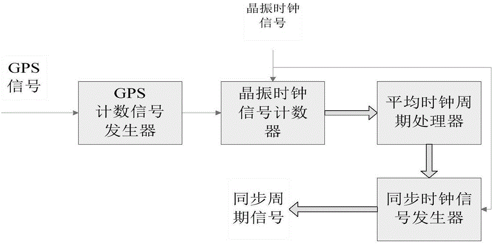
[0016] Such as figure 1 The shown GPS synchronization signal frequency source circuit schematic diagram includes the following signal synchronization processing modules: GPS counting signal generator, crystal oscillator clock signal counter, average clock cycle processor, synchronous clock signal generator, it is characterized in that, the GPS counting The signal generator uses the GPS second pulse as a trigger signal to divide the frequency of the crystal oscillator signal; the crystal oscillator clock signal counter receives the crystal oscillator clock signal, and calculates the average frequency error of the crystal oscillator clock signal through the average clock cycle processing; the synchronization The clock signal generator is used to generate a frequency signal that is synchronized with the GPS second pulse and corrects the frequency error of the crystal oscillator, so as to output a frequency division frequency signal that is synchronized with the GPS second pulse. ...


PUM


Abstract

The invention provides a GPS (Global Positioning system) synchronizing signal frequency source circuit. The GPS synchronizing signal frequency source circuit at least comprises the following signal synchronization processing modules: a GPS counting signal generator, a crystal oscillation clock signal counter, an average clock period processor and a synchronous clock signal generator. The GPS synchronizing signal frequency source circuit is characterized in that the GPS counting signal generator performs frequency division on a crystal oscillation signal by taking a GPS pulse per second as a trigger signal; the crystal oscillation clock signal counter is used for receiving the crystal oscillation clock signal, and calculating an average frequency error of the crystal oscillation clock signal through average clock period processing; and the synchronous clock signal generator is used for generating a frequency signal which is synchronous to the GPS pulse per second and correcting a crystal oscillation frequency error in order to output a frequency division frequency signal which is synchronous to the GPS pulse per second. Through adoption of the GPS synchronizing signal frequency source circuit, the problems that a crystal oscillation frequency signal cannot be synchronous to the GPS pulse per second and an output alternating-current signal is distorted in an existing throughput pulse method are solved, and a technical basis is laid for the realization of a time synchronization standard source.

Description

technical field [0001] The invention relates to the field of digital frequency synthesizers, in particular to a GPS synchronization signal frequency source circuit. Background technique [0002] Existing direct digital frequency synthesizers basically use a high-stable crystal oscillator as the frequency signal source. The high-stable crystal oscillator has the problem of frequency offset over time, and the output frequency signal is not synchronized with the GPS second pulse, so it cannot generate Frequency signal synchronized with GPS second pulse. [0003] In order to correct the frequency offset error of the high-stable crystal oscillator, the commonly used method is the throughput pulse method, that is, the error is evenly distributed into one clock cycle. For example, when the error is 20Hz and the crystal oscillator period is 100MHz, an extra count or One pulse cycle signal is undercounted. But this will lead to a very serious problem, that is, the clock cycle is un...

Claims


Application Information

Patent Timeline
IPC IPC(8): H04J1/06
CPCH04J1/06
Inventor 裴茂林熊茹谢三军肖红霞陈琛罗耀明
Owner STATE GRID CORP OF CHINA
Why Eureka
Try Eureka