Supercharge Your Innovation With Domain-Expert AI Agents!

Flue gas sampling device and method

A flue gas sampling and heating device technology, applied in sampling devices, sampling, measuring devices and other directions, to achieve the effect of improving sampling accuracy, sampling accuracy and instrument service life

Active Publication Date: 2019-03-01
HUADIAN ELECTRIC POWER SCI INST CO LTD
View PDF12 Cites 0 Cited by
  • Summary
  • Abstract
  • Description
  • Claims
  • Application Information

AI Technical Summary

Problems solved by technology

[0005] The technical problem to be solved by the present invention is to provide a flue gas sampling device that accelerates the flue gas in the axial direction to obtain a sufficiently high speed, and separates the required gas samples through the high-speed flue gas, thereby solving the problem of dust in the flue gas sampling process. and the influence of moisture on sampling, to achieve accurate measurement and prolong the service life of the instrument

Method used


Image

  • Flue gas sampling device and method
  • Flue gas sampling device and method

Examples


Embodiment 1

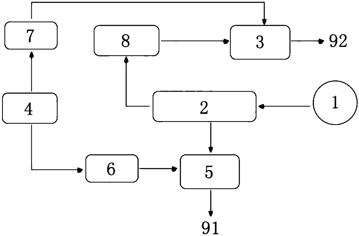
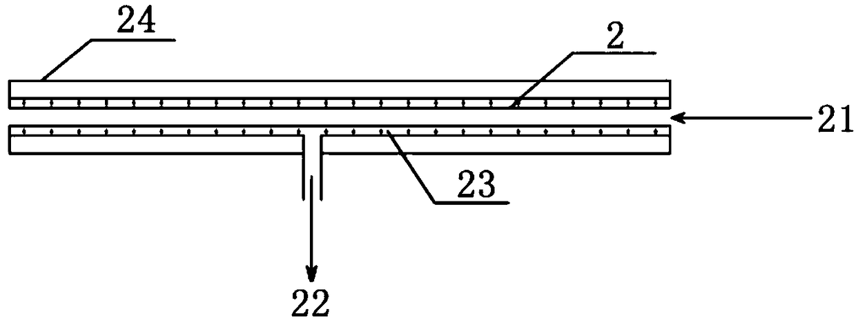
[0029] Such as Figures 1 to 2 As shown, this embodiment is composed of a sampling point 1, a high-speed flue gas sampling pipe 2, a gas injection device 3 and a gas supply device 4, wherein the sampling point 1 is connected to the high-speed flue gas sampling pipe 2, and the gas injection device 3 is a jet pump. The supply device 4 provides compressed air for the gas injection device 3, so that the sampling gas entering the high-speed flue gas sampling pipe 2 from the sampling point 1 reaches an axial flow of 20-30 m / s, and accelerates the dust in the sampling gas; high-speed flue gas sampling The pipe 2 includes a dust-containing channel 21 and a dust-free channel 22 , the dust-containing channel 21 is arranged in the direction of the sampled gas inflow from the sampling point 1 , and the dust-free channel 22 is connected and perpendicular to the dust-containing channel 21 . When the sample gas passes through the dust-containing channel 21, the dust in the high-speed airflow...

Embodiment 2

[0031] Such as Figures 1 to 2 As shown, embodiment 2 adds a heating device 23 and a protective sleeve 24 on the basis of embodiment 1. The high-speed flue gas sampling pipe 2 is composed of a stainless steel pipe plus an inert coating. The selection of the inert coating does not affect the flue gas composition. Just react. The heating device 23 is arranged outside the high-speed flue gas sampling pipe 2, and the high-speed flue gas sampling pipe 2 and the heating device 23 are connected by heat-conducting silicone grease. A protective sleeve 24 is also provided outside the heating device 23 and the high-speed flue gas sampling pipe 2 .

Embodiment 3

[0033] Such as Figures 1 to 2 As shown, embodiment 3 increases the mixing box 5, the first control switch 6, the second control switch 7 and the pressure measuring device 8 on the basis of embodiment 2, the mixing box 5 is an airtight container, respectively connected with the dust-free passage 22 1. The gas supply device 4 is connected to the detection gas outlet 91. After the dust-free sample gas is extracted from the dust-free channel 22, it first enters the mixing box 5 and is diluted with the gas provided by the gas supply device 4, and then is discharged through the detection gas outlet 91. The gas supply device 4 and the mixing box 5 are connected through a first control switch 6, and the first control switch 6 is a proportional valve for controlling the degree of dilution. The gas supply device 4 and the gas injection device 3 are connected through the second control switch 7, the second control switch 7 is a proportional valve used to control the gas flow acceleratio...


PUM


Abstract

The invention relates to a flue gas sampling device and a method thereof. The structure of the flue gas sampling device comprises a sampling point, a high-speed flue gas sampling tube, a gas jet apparatus and a gas supply device. The sampling point is connected to the high-speed flue gas sampling tube. The gas supply device provides the gas jet apparatus with power. The gas jet apparatus is used for accelerating sampled gas. The high-speed flue gas sampling tube contains a dust-containing channel and a dust-free channel. The dust-containing channel is communicated with the sampling point and the gas jet apparatus. The dust-free channel and the dust-containing channel intersect and are communicated with each other. High-speed axial gas flow is generated by the gas jet apparatus, and dust in the sampled gas is accelerated enough in the axial direction. When the sampled gas passes through the dust-containing channel, dust in the high-speed gas flow moves forward in the axial direction while a small part of dust-free sampled gas with low radial velocity passes through the tube wall to be discharged out of the dust-free channel. Then, flue gas is separated from dust.

Description

technical field [0001] The invention relates to a detection device and method, in particular to a flue gas sampling device and method. Background technique [0002] Power plant boilers will produce a large amount of high-temperature flue gas during the combustion process, which contains a large amount of dust, NOx, SO2, Hg and other pollutants. Therefore, various countries in the world have set emission limits for different pollutants for coal-fired flue gas. In order to meet different emission limits, a series of flue gas treatment facilities are installed at the tail of coal-fired power plant boilers, such as SCR flue gas Denitrification devices, electrostatic precipitators, wet desulfurization devices, etc., in order to accurately monitor whether the flue gas after treatment by various environmental protection treatment facilities meets the requirements of national standards, online flue gas monitoring devices are generally installed before and after each flue gas polluta...

Claims


Application Information

Patent Timeline
Patent Type & Authority Patents(China)
IPC IPC(8): G01N1/22
CPCG01N1/2211G01N1/2258
Inventor 何胜李乾坤刘沛奇郑文广李鹏辉张鑫
Owner HUADIAN ELECTRIC POWER SCI INST CO LTD
Features
  • R&D
  • Intellectual Property
  • Life Sciences
  • Materials
  • Tech Scout
  • Unparalleled Data Quality
  • Higher Quality Content
  • 60% Fewer Hallucinations
Learn More