
Sensor fiber sound emission integrated sensing system and method for monitoring safety of structural body

A sensing optical fiber and sensing system technology, which is applied in the field of distributed sensing optical fiber acoustic emission control devices for sensing structural performance degradation, can solve the problems of short signal transmission distance, less monitoring content, poor resistance to electrical measurement interference, etc. The effect of engineering practical ability, improving monitoring accuracy and reducing monitoring cost

Active Publication Date: 2016-10-26
HOHAI UNIV
View PDF4 Cites 8 Cited by
  • Summary
  • Abstract
  • Description
  • Claims
  • Application Information

AI Technical Summary

Problems solved by technology

[0002] Optical fiber sensing technology uses light waves as sensing signals and optical fibers as transmission carriers to perceive and detect external measured signals. It has advantages that traditional electrical sensors do not have in terms of sensing methods, sensing principles, and signal detection and processing. Compared with traditional sensing elements, optical fiber sensing technology has the advantages of anti-electromagnetic interference, anti-chemical corrosion, anti-radiation performance, and it is not charged, small in size, light in weight, and easy to bend. In 1977, the US Naval Research Institute (NRL) began to implement the Foss project (fiber optic sensor system) chaired by Dr. Charles M.Davis. Since then, fiber optic sensors have come out, and subsequent technologies such as OTDR, BOTDA, and FBG have been continuously proposed, and fiber optic sensing technology has been paid more and more attention. However, due to factors such as low spatial resolution and high optical loss over large transmission distances, it seriously hinders the development of optical fiber sensing technology towards miniaturization, remoteness, distribution, and high precision;
[0003] When external factors such as stress, temperature, corrosion, and load interfere with the concrete structure, fractures or deformations will occur inside the material. At this time, the structure will release elastic energy, which is also acoustic emission. In essence, acoustic emission technology, It is to use some acoustic emission sensors to perceive and collect these acoustic emission signals, to infer possible damage and destruction in the structure by storing and analyzing these acoustic emission signals, and finally to judge the service behavior of the concrete structure. Acoustic emission technology It has the advantages of dynamics, sensitivity, and integrity, but there are still many defects, such as short signal transmission distance, less monitoring content, and poor anti-electromagnetic interference ability, which seriously hinder its development;
[0004] The traditional piezoelectric ceramic acoustic emission detection method has mature technology and simple operation, but it also has many disadvantages, such as relatively large system, too many cables, and poor ability to resist electrical interference. For this reason, a new type of optical fiber has been produced. The Bragg grating type acoustic emission detection system has high sensitivity and strong anti-electromagnetic interference ability, but this method also has serious problems. It still belongs to the current relatively traditional point-type monitoring, which is far from meeting the requirements of current large structures, Wide monitoring range, long-distance transmission and other problems, so it is necessary to develop a new type of distributed sensing fiber optic acoustic emission monitoring and detection system

Method used


Image

  • Sensor fiber sound emission integrated sensing system and method for monitoring safety of structural body
  • Sensor fiber sound emission integrated sensing system and method for monitoring safety of structural body
  • Sensor fiber sound emission integrated sensing system and method for monitoring safety of structural body

Examples


Embodiment Construction

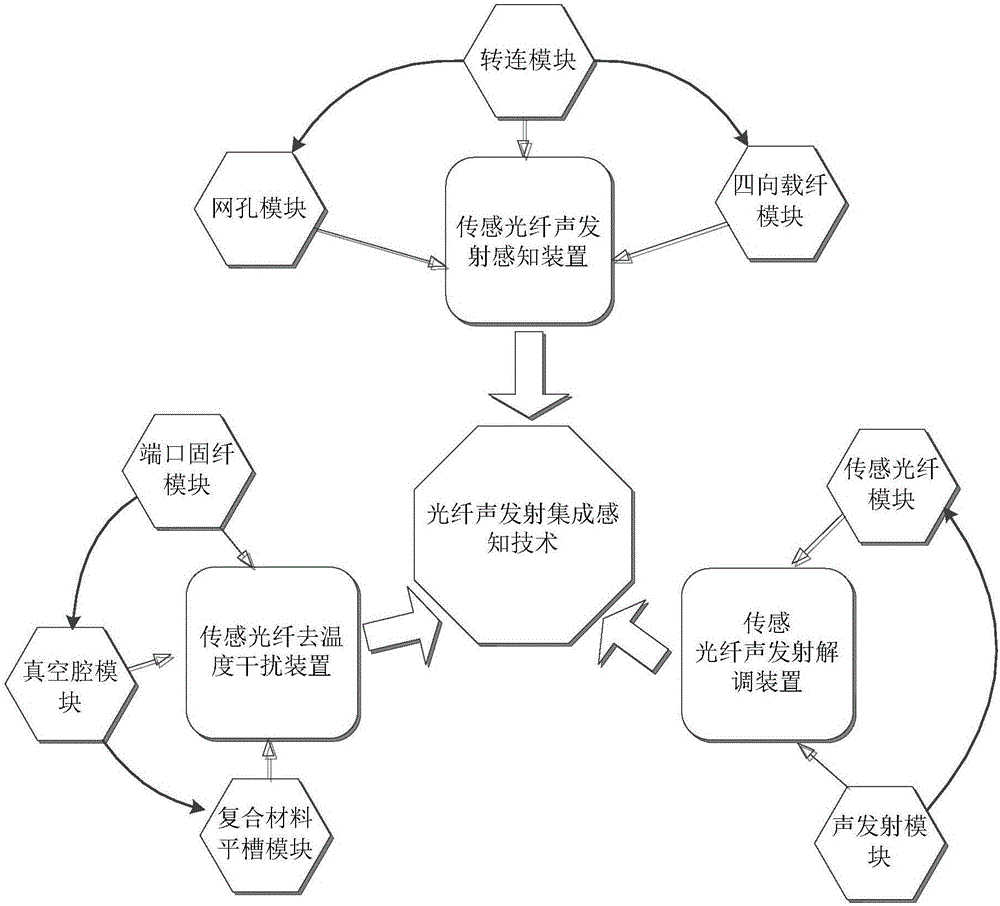
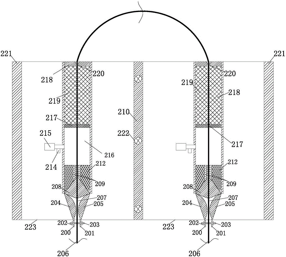
[0029] like Figure 1 to Figure 6 As shown, the sensing optical fiber acoustic emission integrated sensing system for monitoring structure safety of the present invention includes a sensing optical fiber temperature interference removal device and a sensing optical fiber acoustic emission demodulation device, and the sensing optical fiber passes through the sensing optical fiber in turn to remove temperature interference device and sensing optical fiber acoustic emission demodulation device.

[0030] The sensing optical fiber temperature interference removal device includes a vacuum chamber module, a composite material flat groove module, and a port-fixed fiber module. The vacuum chamber module and the composite material flat groove module are connected by a cover plate 217 with a side length of 2 cm. The vacuum chamber module is connected by a four-corner plug with a length of 2cm between each apex, and the composite material flat groove module is connected with the port-fixe...


PUM

PropertyMeasurementUnit
lengthaaaaaaaaaa

Abstract

The invention discloses a sensor fiber sound emission integrated sensing system and method for monitoring the safety of a structural body. The system comprises a sensor fiber temperature interference shielding device and a sensor fiber sound emission demodulating device, wherein a sensor fiber sequentially penetrates through the sensor fiber temperature interference shielding device and the sensor fiber sound emission demodulating device. According to the system, a distributed sensor fiber sound emission regulation and control device for sensing the structural performance degradation is integrated with a sensor fiber sound emission sensing system with multiple complex devices, functional modules and interconnected components, the sensor fiber sound emission integrated sensing system and the sensor fiber sound emission integrated sensing method which are integrated with femtosecond laser pulse and acoustic emission techniques, multistage time delay of multi-sound emission wave common-cavity holes under multistage physical size and multi-sound wave vibration frequency are initiated and disclosed, a novel technique integrated with multistage high-precision identified monitoring and detection is realized, and the streamlined and automatic application can be realized. The system and the method have greater superiorities in aspects of lowering the monitoring cost, improving the monitoring precision and practical capacity of engineering, and the like.

Description

technical field [0001] The invention relates to a distributed sensing optical fiber acoustic emission control device and method for sensing structural performance degradation, and belongs to the field of safety monitoring and detection of water engineering structures. Background technique [0002] Optical fiber sensing technology uses light waves as sensing signals and optical fibers as transmission carriers to perceive and detect external measured signals. It has advantages that traditional electrical sensors do not have in terms of sensing methods, sensing principles, and signal detection and processing. Compared with traditional sensing elements, optical fiber sensing technology has the advantages of anti-electromagnetic interference, anti-chemical corrosion, anti-radiation performance, and it is not charged, small in size, light in weight, and easy to bend. In 1977, the US Naval Research Institute (NRL) began to implement the Foss project (fiber optic sensor system) chai...

Claims


Application Information

Patent Timeline
Patent Type & Authority Applications(China)
IPC IPC(8): G01N29/14G01N29/04G01H9/00
CPCG01H9/004G01N29/04G01N29/14G01N2291/0232G01N2291/0258G01H9/00G01N29/2418G01N29/4463
Inventor 苏怀智杨孟顾冲时
Owner HOHAI UNIV
Learn More