A High-Gain Full-Bridge Isolated DC Converter with Multi-unit Diode Capacitor Network

A diode capacitor, DC converter technology, applied in the direction of converting DC power input to DC power output, adjusting electrical variables, and high-efficiency power electronic conversion, can solve power semiconductor device turn-off voltage spikes, affect transformer linearity, increase Device voltage stress and other issues, to achieve the effect of improving power conversion efficiency, increasing power density, and reducing voltage stress

Active Publication Date: 2018-01-19
山东隽宇电子科技有限公司
View PDF2 Cites 0 Cited by
  • Summary
  • Abstract
  • Description
  • Claims
  • Application Information

AI Technical Summary

Problems solved by technology

However, due to the influence of parasitic parameters in the inductance loop of the main circuit and the performance of the controller, even if the duty cycle reaches the limit state close to 1, it is difficult to have a high voltage gain
The diode conducts in a very short time and bears relatively large voltage and current stress, which will inevitably lead to serious switching loss and EMI problems
Its existing technology is relatively mature and easy to implement
However, an excessively high turns ratio will affect the linearity of the transformer, cause serious magnetic flux leakage and bias problems, and increase the volume and leakage inductance, which will cause the turn-off voltage peak of the power semiconductor device, increase the voltage stress of the device, and reduce the conversion device efficiency

Method used


Image

  • A High-Gain Full-Bridge Isolated DC Converter with Multi-unit Diode Capacitor Network
  • A High-Gain Full-Bridge Isolated DC Converter with Multi-unit Diode Capacitor Network
  • A High-Gain Full-Bridge Isolated DC Converter with Multi-unit Diode Capacitor Network

Examples


Embodiment Construction

[0034] The present invention is described in further detail below in conjunction with accompanying drawing:

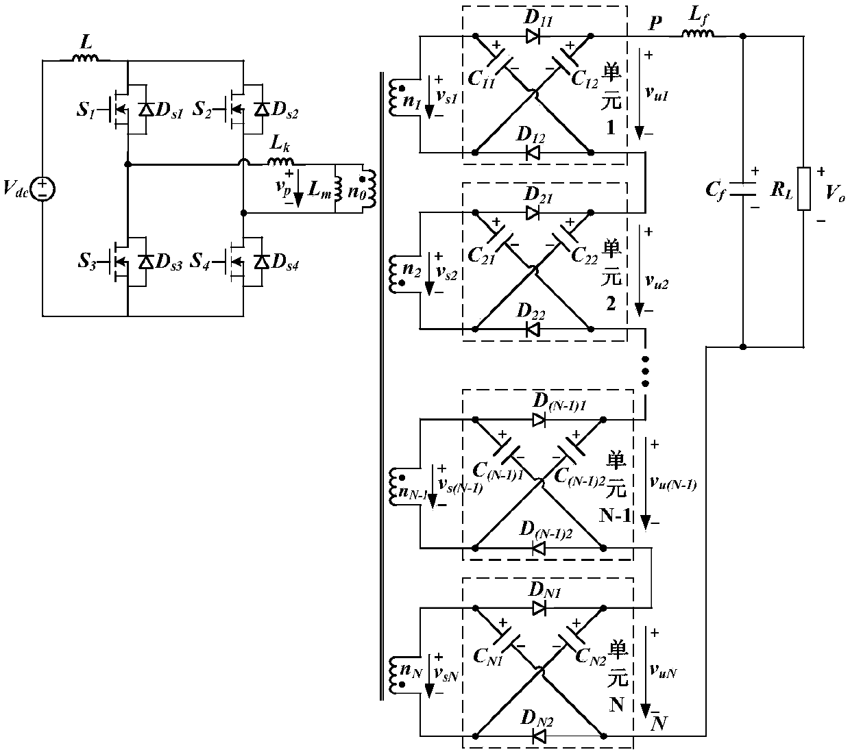
[0035] see figure 2 , the present invention includes the input power supply V dc , boost inductor L, full-bridge inverter circuit, transformer T with multiple windings on the secondary side, multiple two-port diode capacitor boost units, LC filter circuit and output load R L ; The full-bridge inverter circuit includes four controllable switching tubes IGBT or MOSFET and body diode D; the transformer T can be equivalent to an ideal transformer with a fixed ratio and an excitation inductance L m After parallel connection, it is equivalent to the leakage inductance L of the primary side k series; LC filter circuit consists of filter inductor L f and filter capacitor C f composition; input power supply V dc The positive pole is connected to the positive pole of the DC side of the full-bridge inverter circuit through the boost inductor L, and the input power V dc The...


PUM


Abstract

The present invention discloses a multi-unit diode capacitor network high-gain full-bridge isolated direct current converter. A transformer T is connected with an excitation inductor Lm in parallel and is connected with the leakage inductor Lk equivalent to the edge in series; an LC filtering circuit is composed of a filtering circuit Lf and a filtering capacitor Cf; and the anode of an input power supply Vdc is connected with the direct current side anode of a full-bridge inversion circuit, the cathode of the input power supply Vdc is connected with the cathode of the full-bridge inversion circuit direct current side, and a boost full-bridge inversion circuit is formed. The multi-unit diode capacitor network high-gain full-bridge isolated direct current converter can improve the voltage gain, obtain high voltage gain, reduce the voltage stress of a power device, reduce the turn ratio of a transformer, reduce the size of a magnetic element and improve the power density. The multi-unit diode capacitor network high-gain full-bridge isolated direct current converter employs the transformer leakage inductor and the circuit resonance to realize the zero current switching (ZCS) of a main power device to reduce the switch loss and improve the electric energy transition efficiency. The multi-unit diode capacitor network high-gain full-bridge isolated direct current converter has a wide application prospect in a new energy distributed power generation system.

Description

【Technical field】 [0001] The invention belongs to the field of distributed power generation such as new energy photovoltaics and fuel cells, and relates to a high-gain isolated DC conversion technology, in particular to a multi-unit diode capacitor network high-gain isolated full-bridge DC converter. 【Background technique】 [0002] The development and utilization of green energy such as solar energy and fuel cells has important strategic significance for optimizing my country's energy structure and achieving sustainable economic and environmental development. Different from traditional DC power sources, such as DC generators and storage batteries, photovoltaics and fuel cells have the characteristics of low output voltage and obvious voltage drop. One of the many technical bottlenecks in the system. [0003] Typical photovoltaic and fuel cell power generation systems are divided into two types: single-stage and two-stage. The single-stage structure inverter (DC-AC) only un...

Claims


Application Information

Patent Timeline
Patent Type & Authority Patents(China)
IPC IPC(8): H02M3/335H02M3/338
CPCH02M3/3353H02M3/3381Y02B70/10
Inventor 张岩缪哲语刘进军李新颖李富安
Owner 山东隽宇电子科技有限公司
Why Eureka
Try Eureka