Greasy dirt-resistant oil-water separator

An oil-water separation device and anti-fouling technology, which is applied in the direction of separation methods, liquid separation, grease/oily substance/floating matter removal devices, etc., can solve the problems of poor anti-fouling and clogging performance of organic membranes and poor removal effect that are not suitable for large-scale application. Ideal and other issues, to achieve good oil-water separation effect, good anti-fouling performance, and improve separation efficiency and effect

Active Publication Date: 2016-11-02
湖州深净环境科技有限公司
View PDF4 Cites 3 Cited by
  • Summary
  • Abstract
  • Description
  • Claims
  • Application Information

AI Technical Summary

Problems solved by technology

Emulsified oil is very fine oil droplets with a particle size of 0.1-10 μm. Due to the presence of surfactants at the oil-water interface, it is usually stably dispersed in water in the form of oil-in-water, and it is difficult to separate. Traditional removal of oily sewage Oil technology is not ideal for the removal of emulsified oil, and often supplemented by electrolysis, flocculation and other pre-emulsification processes, which consume a lot of energy and materials
[0004] In addition, another existing oil-water separation process is membrane (organic membrane) method, but in this operation process, it is necessary to maintain the high permeation flux of the organic membrane. Not only is the operation inconvenient, but also the separation efficiency is low, so it is not suitable for actual large-scale application

Method used


Image

  • Greasy dirt-resistant oil-water separator
  • Greasy dirt-resistant oil-water separator
  • Greasy dirt-resistant oil-water separator

Examples


Embodiment Construction

[0026] The present invention will be further described below in conjunction with the accompanying drawings and specific embodiments.

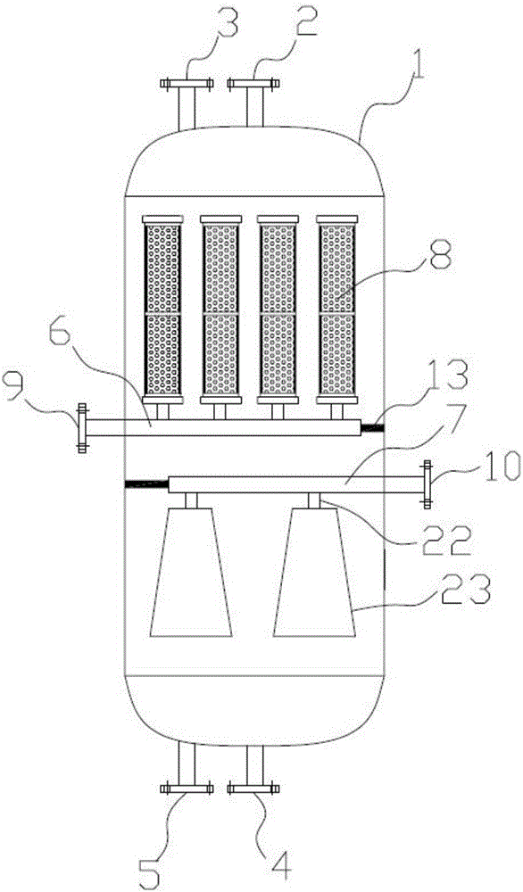
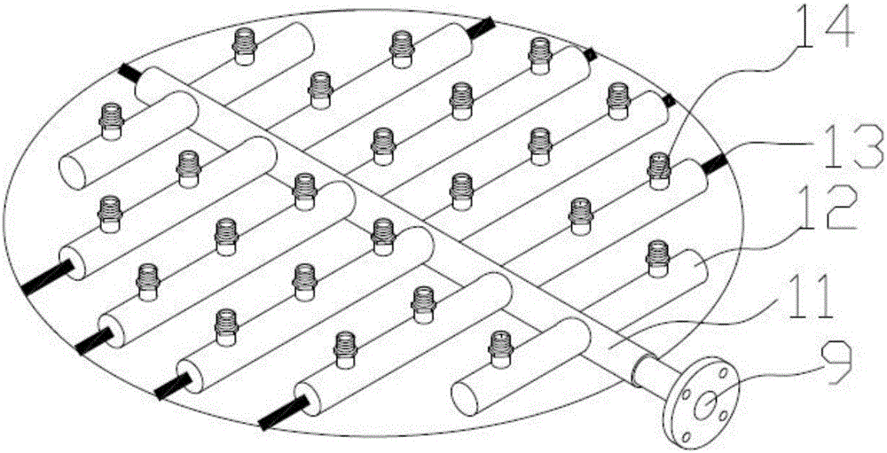
[0027] Such as figure 1 A pollution-resistant oil-water separation device shown includes a tank body 1, a water inlet water device 6, a water outlet water device 7 located below the water outlet water device, a columnar oil-water separation filter element 8 and an outlet water diversion mechanism, and the top of the tank body There is a light oil discharge port 2 and a backwash air inlet 3 for connecting compressed air. The bottom of the tank is provided with a heavy oil discharge port 4 and a sewage discharge port 5. The water inlet water device and the water outlet water device are fixed on the In the tank body, the side wall of the tank body is provided with a water inlet 9 and a water outlet 10, and the water inlet water device includes a water inlet main pipe 11 and a water inlet branch pipe 12 (see figure 2 ), the water inlet main pipe ...


PUM

PropertyMeasurementUnit
particle sizeaaaaaaaaaa

Abstract

The invention discloses a greasy dirt-resistant oil-water separator. The greasy dirt-resistant oil-water separator comprises a tank, the top of the tank is provided with a light oil outlet and a backwashing air inlet for compressed air connection and the bottom of the tank is provided with a heavy oil discharge outlet and a sewage draining outlet. The greasy dirt-resistant oil-water separator also comprises an inlet water separator, an outlet water separator below the inlet water separator, a cylindrical oil-water separation filter core and an outlet water diversion mechanism. The inlet water separator and the outlet water separator are fixed in the tank. The side wall of the tank is provided with a water inlet and a water outlet. The water inlet and the inlet water separator are connected. The water outlet is connected to the outlet water separator. The cylindrical oil-water separation filter core is fixed to the inlet water separator and is communicated with the inlet water separator. The outlet water diversion mechanism is fixed to the bottom of the outlet water separator and is communicated with the outlet water separator. The greasy dirt-resistant oil-water separator has the advantages of small land occupation area, safety, reliability, simple processes, low operation power consumption, wide application range, good dirt blocking resistance, cleaning easiness, long service life, good oil-water separation effects and high separation efficiency.

Description

technical field [0001] The present invention relates to the technical field of oil-water separation, in particular to a kind of pollution-resistant water for oily sewage such as coal-to-oil Fischer-Tropsch synthetic water, coal gasification sewage, semi-coke sewage, oil shale sewage, oily sewage in oil fields, and oily sewage in machining. Oil-water separation device. Background technique [0002] Oily wastewater is a common industrial wastewater. With the rapid development of the national economy, the amount of oily wastewater produced by many industries such as petroleum exploration, petroleum processing, and mechanical processing is also increasing. The harm caused by oily wastewater to the environment is also increasing. The hazards of oily wastewater are mainly manifested in the following aspects: ① affects drinking water resources and groundwater resources, and endangers aquatic resources; ② endangers human health; ③ pollutes the atmosphere; ④ affects crop production;...

Claims


Application Information

Patent Timeline
Patent Type & Authority Applications(China)
IPC IPC(8): C02F1/40C02F1/44
CPCC02F1/40C02F1/44
Inventor 钟山云叶震杜松赵崇毅段锋刘剑刘雷王小明
Owner 湖州深净环境科技有限公司
Why Eureka
Try Eureka