

Well completion method with reservoir protection and packing functions
A reservoir and functional technology, applied in the field of completion methods with the function of protecting reservoir isolation, can solve problems such as pressure penetration, exceeding the reservoir, and many processes, so as to improve the absorption capacity and seepage capacity, and protect the isolation function , high economic benefits
- Summary
- Abstract
- Description
- Claims
- Application Information
AI Technical Summary
Problems solved by technology
Method used
Image

Examples
Embodiment 1
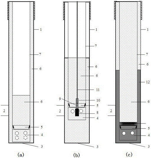
[0044] A well completion method with the function of protecting reservoir isolation. When the reservoir 2 is in an open-hole state, at least one high-energy gas fracturing is performed on at least one layer of the reservoir 2 until the reservoir is cemented. 2 Formation of artificial fractures near the wellbore, including the following steps:
[0045] Step 1: Drilling: drilling through layer reservoir 2 to the full drilling depth;
[0046] Step 2: Perforating: establish a tunnel at a predetermined depth in the near-wellbore zone of reservoir 2;
[0047] Step 3: Block building: establish the design liquid block in the wellbore 1, calculate and determine the high-energy gas fracturing parameters according to the liquid block involved;
[0048] Step 4: high-energy gas fracturing: perform at least one high-energy gas fracturing on at least one layer of reservoir 2, and form artificial fractures in the zone near the wellbore 2;
[0049] Step 5: Cementing: Forming a cement sheath ...
Embodiment 2
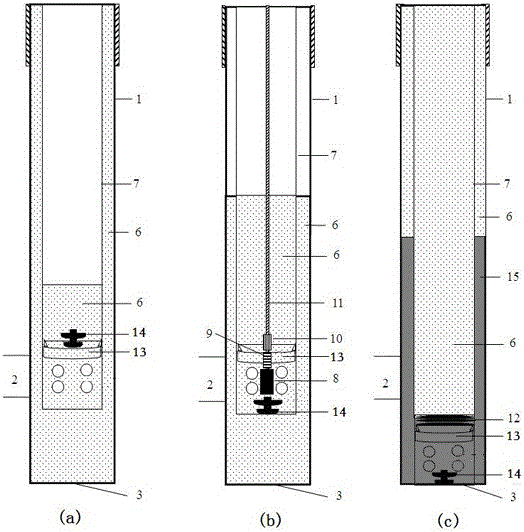
[0055] A well completion method with the function of protecting the reservoir isolation, drilling through the reservoir 2 without drilling to the completion depth, when the reservoir 2 is in an open hole state, performing at least one high-energy gas fracturing on at least one layer of the reservoir 2, Forming artificial fractures in the zone near the wellbore of reservoir 2 includes the following steps:
[0056] Step 1: drilling: drilling through the reservoir 2 without drilling to the full drilling depth;
[0057] Step 2: Perforating: establish a certain-depth tunnel in the near-wellbore area of reservoir 2;
[0058] Step 3: Block building: establish the design liquid block in the wellbore 1, calculate and determine the high-energy gas fracturing parameters according to the liquid block involved;
[0059] Step 4: high-energy gas fracturing: perform at least one high-energy gas fracturing on at least one layer of reservoir 2, and form artificial fractures in the zone near ...
Embodiment 3
[0067] A well completion method with the function of protecting the reservoir isolation. The reservoir 2 is drilled but not penetrated. At least one high-energy gas fracturing to form artificial fractures in the zone near the wellbore of reservoir 2, including the following steps:
[0068] Step 1: drilling: drilling the reservoir 2 without drilling through the reservoir 2;
[0069] Step 2: Perforating: establish a tunnel at a predetermined depth in the near-wellbore zone of reservoir 2;
[0070] Step 3: Block building: establish the design liquid block in the wellbore 1, calculate and determine the high-energy gas fracturing parameters according to the liquid block involved;
[0071] Step 4: high-energy gas fracturing: perform at least one high-energy gas fracturing on the drilled but not penetrated reservoir 2, and form artificial fractures in the zone near the wellbore of the reservoir 2;
[0072] Step 5: Continue drilling to the full drilling depth;
[0073] Step 6: ceme...
PUM
 Abstract
Description
Claims
Application Information