
Tunnel ditch cable trough construction trolley

A technology of water trench cable trough and construction trolley, which is applied in the direction of tunnel, tunnel lining, drainage, etc., can solve the problems of long construction time and damage to the concrete structure of water trench cable trough, achieve short demoulding time, prevent construction errors, The effect of improving construction accuracy

Inactive Publication Date: 2016-11-09
NO 7 ENG CO LTD OF CHINA RAILWAY 19 BUREAU GRP +1
View PDF6 Cites 2 Cited by
  • Summary
  • Abstract
  • Description
  • Claims
  • Application Information

AI Technical Summary

Problems solved by technology

However, since the formwork of the gutter cable trough is a non-load-bearing plate, and all of them adopt an overall closed U-shaped formwork structure, the demoulding method of lifting the U-shaped formwork vertically must overcome the atmospheric pressure caused by airtightness
When the concrete is not completely solidified or the strength is not enough, lifting the U-shaped plate for demoulding will cause large-scale damage to the concrete structure of the trench cable trench, which will cause the existing construction trolley of the trench cable trench to be affected by the concrete strength factor in the demoulding process time. impact, the demoulding time also needs at least 14 hours
Although the construction time of the existing trench cable trough construction trolley is greatly shortened compared with the traditional construction, the overall construction time is still relatively long

Method used


Image

  • Tunnel ditch cable trough construction trolley
  • Tunnel ditch cable trough construction trolley
  • Tunnel ditch cable trough construction trolley

Examples


Embodiment Construction

[0038] Example of construction trolley for tunnel water trench and cable trough:

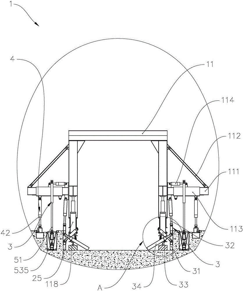
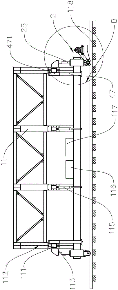
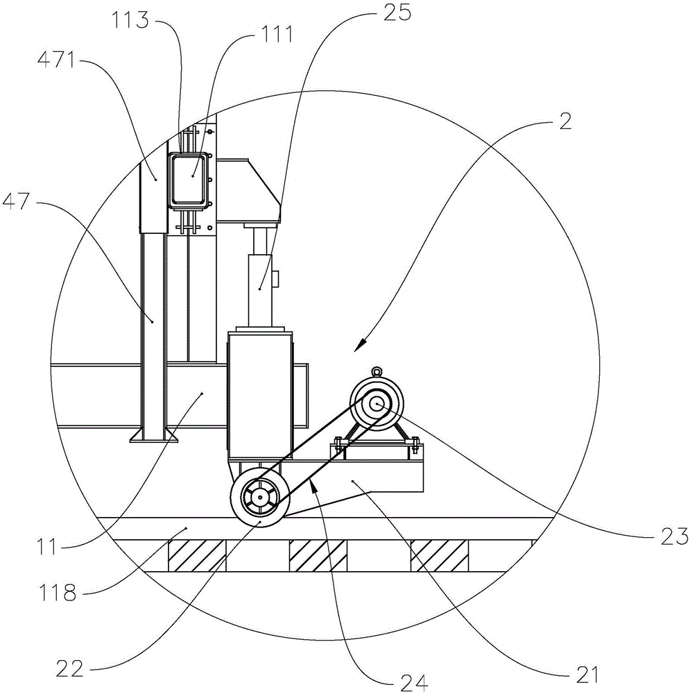
[0039] refer to figure 1 and figure 2 , figure 1 It is a structural schematic diagram of an embodiment of a construction trolley for tunnel ditch and cable trough of the present invention, figure 2 It is a schematic diagram of the relative positions of the truss and the walking system of the embodiment of the construction trolley for tunnel ditch and cable trough of the present invention. Tunnel ditch cable channel construction trolley 1 includes truss 11, power distribution operating system 116, hydraulic control system 117, walking system 2, side wall formwork device 3, cable formwork device 4 and water ditch formwork device 5, wherein, The walking system 2 is installed under the truss 11, the tunnel ditch cable trough construction trolley 1 moves through the walking system 2, the power distribution operating system 116 provides power for the tunnel ditch cable trough construction trolley...


PUM


Abstract

The invention provides a tunnel ditch cable trough construction trolley which comprises a truss and a traveling system installed below the truss. The tunnel ditch cable trough construction trolley further comprises side wall die set devices, cable die set devices and ditch die set devices. Each side wall die set device comprises a side wall die set, a first oil cylinder and a second oil cylinder, wherein the two ends of the first oil cylinder are hinged to the side wall die set and the truss correspondingly, and the two ends of the second oil cylinder are hinged to the side wall die set and the truss correspondingly. Each cable die set device comprises a cable die set and a third oil cylinder, and the two ends of the third oil cylinder are hinged to the cable die set and the truss correspondingly. Each ditch die set device comprises a fourth oil cylinder, two oppositely arranged wedge-shaped die sets and an adjusting unit, wherein the adjusting unit comprises a bearing beam, an adjusting hand wheel and two oppositely arranged threaded rods, the two ends of the fourth oil cylinder are hinged to the truss and the bearing beam correspondingly, the adjusting hand wheel is arranged on the bearing beam, and each threaded rod is connected between the adjusting hand wheel and the corresponding wedge-shaped die set. The construction trolley has the advantages that the construction quality is high, and the demolding time is short.

Description

technical field [0001] The invention relates to the technical field of tunnel construction, in particular to a construction trolley for tunnel water ditch cable channels. Background technique [0002] Tunnel gutter cable trench is an auxiliary project of tunnel construction, generally the last process of tunnel construction, and construction can only be organized in the middle and late stages of tunnel construction, so there are common problems such as large construction volume and tight construction period. At the same time, there are long-term problems such as poor linearity, many construction joints, and difficult construction joints in the construction of concrete for water trenches and cable trenches. Moreover, since the trenches and cable trenches are located on both sides of the tunnel, their appearance quality will directly affect the overall standardization of tunnel construction. Image, so it is one of the key auxiliary projects in the later stage of tunnel constru...

Claims


Application Information

Patent Timeline
Patent Type & Authority Applications(China)
IPC IPC(8): E21D11/10E21F16/02
CPCE21D11/102E21F16/02
Inventor 刘国强刘荣王俊涛周宝春王建伟季军王永生杨新民
Owner NO 7 ENG CO LTD OF CHINA RAILWAY 19 BUREAU GRP
Learn More