Method and device for vertical measurement and correction of molybdenum wire for CNC wire cutting machine

A technology of wire cutting machine and vertical measurement, which is applied in the direction of auxiliary equipment, electric processing equipment, electrode manufacturing, etc., can solve the problems of not fully representing the actual operation of the equipment, large errors in visual inspection methods, and strong dependence, etc., to achieve wire cutting Vertical automatic correction, avoiding measurement errors, and easy operation

Inactive Publication Date: 2018-03-23
SUZHOU UNIV OF SCI & TECH
View PDF9 Cites 0 Cited by
  • Summary
  • Abstract
  • Description
  • Claims
  • Application Information

AI Technical Summary

Problems solved by technology

The above-mentioned molybdenum wire vertical detection method is a method commonly used in wire cutting processing at present. This method mainly has the following disadvantages: 1), due to the use of manual visual inspection, it is highly dependent on human factors such as the technical level and experience of the operator; 2) . The error of the visual inspection method is relatively large, and the consistency of each adjustment cannot be guaranteed, which seriously affects the product quality; 3). Discharge cutting must be carried out during calibration, and the alignment is judged by the uniformity of the electric spark. It is a contact measurement. Due to the effect of discharge force and other factors can easily cause measurement errors
4) Only one direction of the X (or Y) axis can be calibrated vertically at a time, and the worktable must be moved twice to calibrate the other axis, which is prone to measurement errors; 5) Fully automatic vertical calibration cannot be achieved, only According to the current situation, manual vertical correction can be made through U and V axis stepping motors;
[0008] 1. The electronic calibrator can only be detected in a static state, and the wire-moving mechanism is very complicated, and the static state detection alone cannot fully represent the actual operation of the equipment
[0009] 2. The electronic calibrator adopts contact measurement, which is very easy to cause measurement error due to contact with molybdenum wire.
[0010] 3. In order to ensure the "simultaneous" contact of the upper and lower contacts, it is still necessary to visually observe the "simultaneous" lighting of the upper and lower lights, which requires high operator experience, and the consistency cannot be guaranteed, which is likely to cause measurement errors
[0011] 4. After one of the upper and lower contacts is on, the distance between the uncontacted contact and the molybdenum wire is completely visual, that is, the distance between the other contact and the molybdenum wire cannot be known, and it is difficult to adjust
[0012] 5. Only vertical correction in one direction of the X (or Y) axis can be done each time, and the worktable must be moved twice to detect the other axis, which is prone to measurement errors
[0013] 6. Since it is a simple switch value detection, it cannot be connected with the numerical control system to form an automatic vertical correction
[0014] The above problems have not been effectively improved for many years, and the corresponding measurement technology is also very lagging behind

Method used


Image

  • Method and device for vertical measurement and correction of molybdenum wire for CNC wire cutting machine
  • Method and device for vertical measurement and correction of molybdenum wire for CNC wire cutting machine
  • Method and device for vertical measurement and correction of molybdenum wire for CNC wire cutting machine

Examples


Embodiment Construction

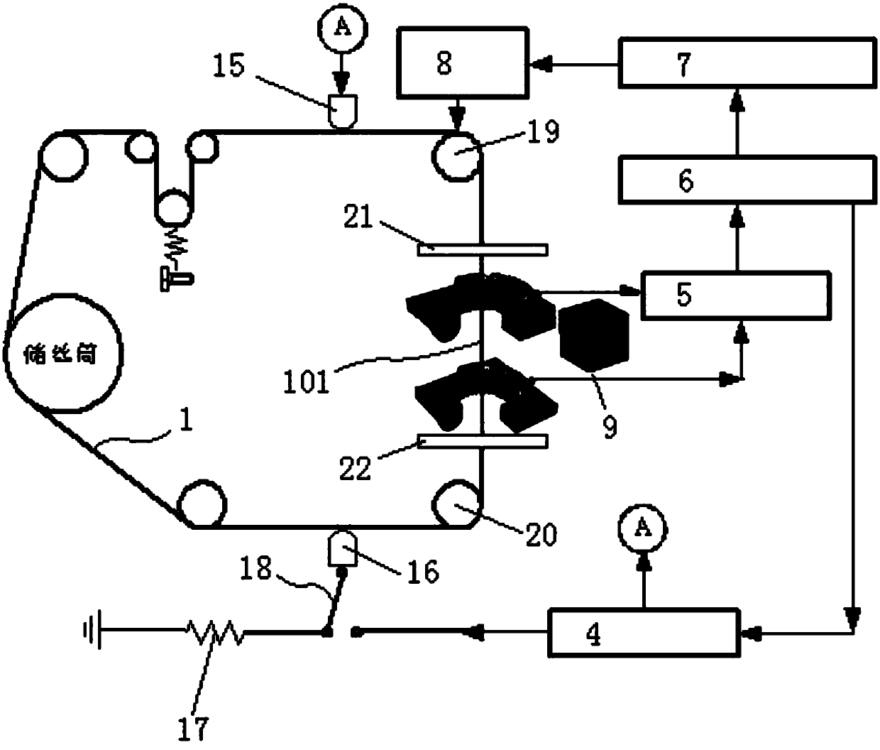
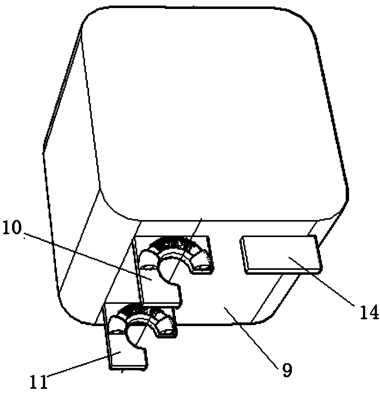
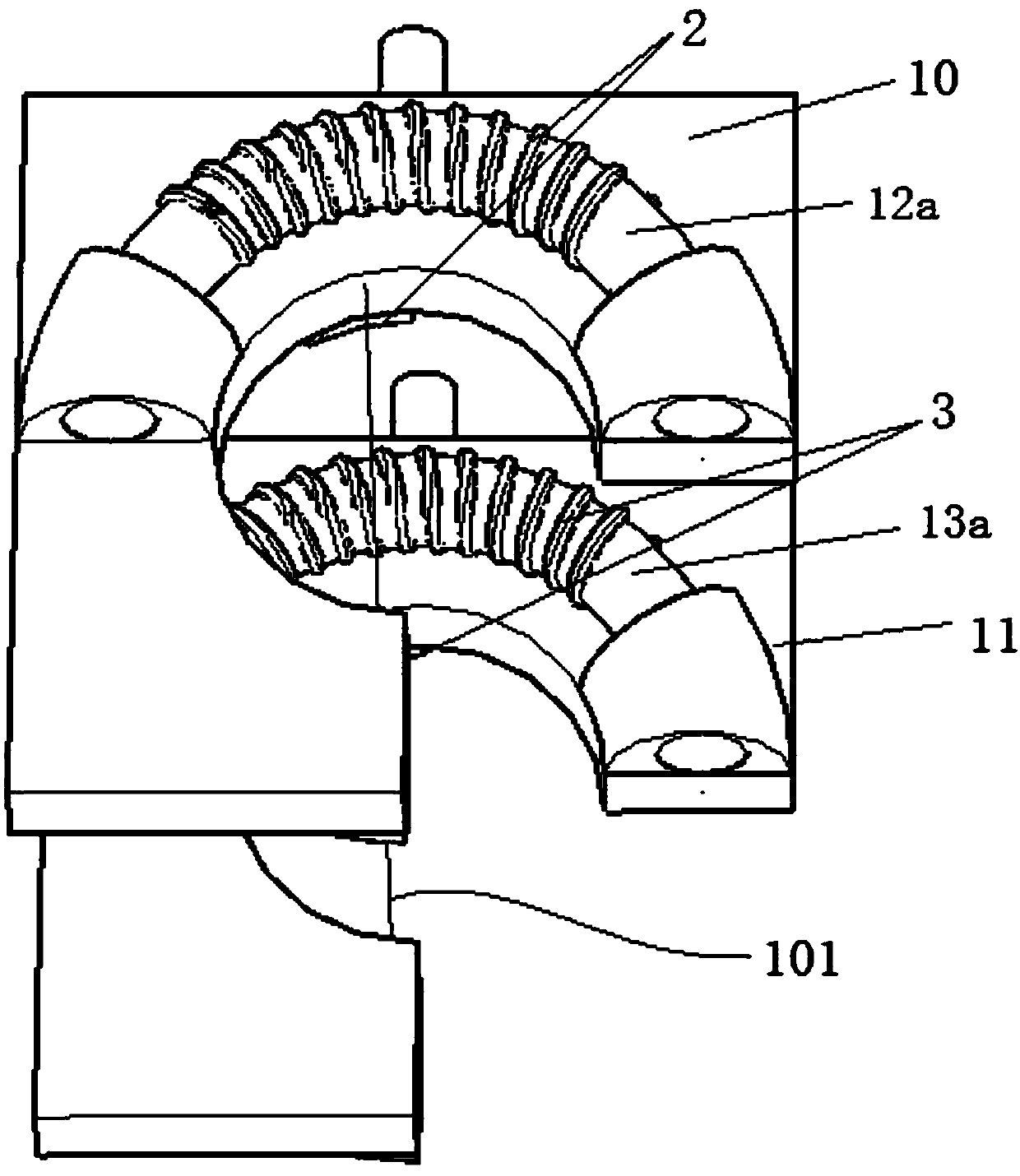
[0051] Figure 1 ~ Figure 4 A specific embodiment of the molybdenum wire vertical measuring and correcting device of the numerically controlled wire cutting machine of the present invention is shown. As everyone knows, the molybdenum wire 1 of the numerically controlled wire cutting machine includes a molybdenum wire linear working section 101 for cutting workpieces, and this device uses It is used to measure and correct the verticality of the molybdenum wire straight working section 101. The CNC wire cutting machine includes a numerical control system 6, a stepping motor 7 connected to the numerical control system, a taper adjustment device 8 connected to the stepping motor, and the taper adjustment device 8 is connected to the upper guide wheel of the molybdenum wire linear working section 101. The actual In application, the stepper motor 7 drives the taper adjustment device 8 to move, and then the position of the upper guide wheel is adjusted through the action of the taper...


PUM


Abstract

The invention discloses a molybdenum wire perpendicular measurement and correction method and device for a numerically-controlled linear cutter. The measurement and correction device comprises upper coil groups, lower coil groups, a high-frequency power supply and a signal processing circuit, wherein the upper coil groups are arranged at the radial outer side of a molybdenum wire linear work section; the lower coil groups are arranged at the radial outer side of the molybdenum wire linear work section and distributed below the upper coil groups at intervals, the structures of the lower coil groups and the upper coil groups are identical, and the lower coil groups and the upper coil groups are distributed in a coinciding manner in a vertical direction; the high-frequency power supply connects high-frequency pulse current into the molybdenum wire linear work section, produces an alternating magnetic field around the molybdenum wire linear work section, and accordingly, produces induction voltage in the upper coil groups and the lower coil groups; and the signal processing circuit is connected with both the upper coil groups and the lower coil groups and can acquire and compare induction voltage in the upper coil groups and the lower coil groups. The device can realize the simultaneous non-contact measurement of the perpendicularity of the molybdenum wire in the two directions of X and Y axes and avoids errors caused by the secondary movement of a working table.

Description

technical field [0001] The invention relates to the field of wire cutting machine tools, in particular to a method and device for vertical measurement and correction of molybdenum wires of a numerically controlled wire cutting machine. Background technique [0002] Wire cutting process is to use continuously moving thin metal wire as electrode to perform pulse spark discharge on the workpiece to etch metal or cut into shape. This equipment is mainly used for processing superhard steel, hard alloy, various complex and precise workpieces. . Electrode wire is a thin metal wire made of precious metals such as molybdenum (usually called molybdenum wire, this patent is mainly used for fast wire cutting machine tools), molybdenum wire discharges through the medium (electrolyte) and the workpiece, corroding the metal to reach The purpose of cutting and forming. [0003] In recent years, with the continuous development of automation technology, various CNC wire cutting equipment ha...

Claims


Application Information

Patent Timeline
Patent Type & Authority Patents(China)
IPC IPC(8): B23H7/02B23H7/08B23H11/00
CPCB23H7/02B23H7/08B23H11/00
Inventor 李学哲李爽
Owner SUZHOU UNIV OF SCI & TECH
Why Eureka
Try Eureka