
Fabric deburring device

A kind of raw edge and fabric technology, which is applied in the direction of fabric edge trimming, fabric surface trimming, textile and paper making, etc. It can solve the problems of easy fire alarm, low cutting efficiency, and non-straight cutting edge, so as to improve work efficiency and product quality. Good effect and fast excision effect

Active Publication Date: 2017-09-19
常州宏大智慧科技有限公司
View PDF8 Cites 0 Cited by
  • Summary
  • Abstract
  • Description
  • Claims
  • Application Information

AI Technical Summary

Problems solved by technology

But above-mentioned two kinds of excision methods all have deficiencies: electric heating cutter can't be suitable for all kinds of fabrics, as for such as pure cotton, acrylic fiber etc. its ignition point is not high, and the afterburning property is good, and the contact surface of burr and air Large, it is easy to cause fire; but for fabrics with heavy weight and high ignition point, the speed of the equipment cannot be increased when cutting burrs with an electric cutter, which makes the cutting efficiency low; some chemical fibers will melt and shrink when cut with an electric cutter In this way, there may be a notch at the cutting line, and it is very easy to cause the fabric to tear from the notch of the selvage during the subsequent fabric expansion process; and if the fabric burr is cut off manually with a knife, It makes the edge trimming not straight, and the labor intensity is high and the efficiency is low. At the same time, the manual trimming process is not safe, which increases safety hazards.
Therefore, the existing edge hair removal method greatly affects the normal operation of the inkjet printing process and affects the entire production efficiency.
[0004] At the same time, in the prior art, especially when the shuttleless machine forms the fabric, since the package yarn fixed by the weft yarn reel is unidirectional weft insertion, the two ends of each weft yarn are free ends, and the formed selvedge is also a burr. During the weaving process, the raw edges tend to be upturned or lie down on the cloth surface, that is, the state of the raw edges is irregular. When the raw edges are upturned, the weft yarn (false yarn side yarn) cannot be cut well, which will directly affect the subsequent inkjet printing effect

Method used


Image

  • Fabric deburring device
  • Fabric deburring device
  • Fabric deburring device

Examples


Embodiment 1

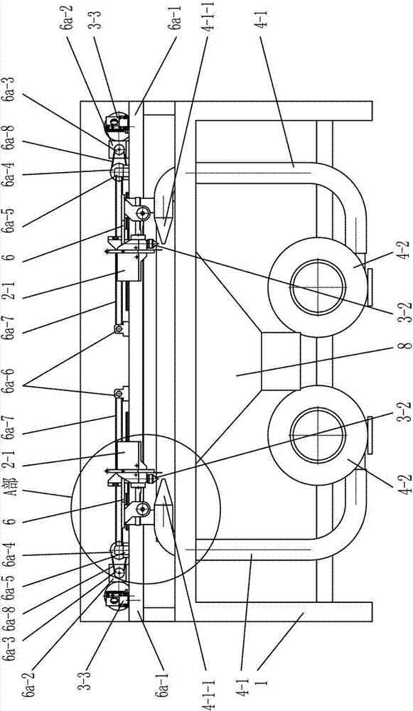
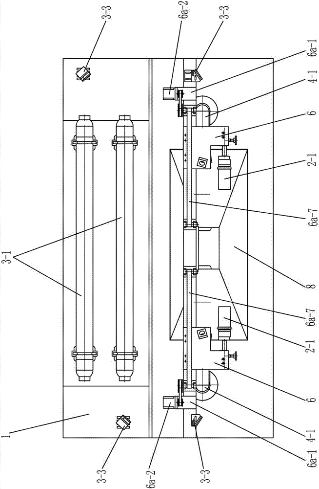
[0041] Such as Figure 1~13 As shown, a fabric burr cutting device includes a frame 1, and a fabric edge detecting mechanism and an edge detecting and cutting transmission mechanism arranged at both ends of the frame 1;

[0042] The transmission mechanism for edge detection and cutting includes a moving carriage 6;

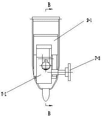
[0043] The fabric edge detection mechanism includes a position detector 2-1, and the position detector 2-1 is installed on the movable support plate 6 of the edge detection and cutting transmission mechanism;

[0044] It also includes a laser cutting mechanism and a burr finishing mechanism, the laser cutting mechanism includes a laser tube 3-1, a laser cutting head 3-2 and a laser reflector 3-3, and the laser tube 3-1 and the laser reflector 3-3 All are fixed on the frame 1, and the movable carriage 6 of the edge detection and cutting transmission mechanism at both ends of the frame 1 is provided with a laser cutting head 3-2;

[0045] The laser light emitted b...

Embodiment 2

[0054] Such as Figure 14 , 15 , 16, and 17, the difference between embodiment 2 and embodiment 1 is: a fabric burr cutting device, the burr finishing mechanism includes a motor 5-1, a driving brush wheel 5-2, a driven brush Wheel 5-3 and suction hair installation bracket 5-4, the motor shaft of described motor 5-1 is provided with active hair brush wheel 5-2, and described suction hair installation bracket 5-4 is fixed on the mobile dragging of edge cutting transmission mechanism. On the plate 6, the active brush wheel 5-2 and the driven brush wheel 5-3 are arranged up and down on the hair-absorbing installation bracket 5-4, and are rotatably connected with the hair-absorbing installation bracket 5-4.

[0055] The burr finishing mechanism in Example 2 combs the burr of the fabric through the brush wheel to make it straight, not upturned, and not curled, so that laser cutting can be performed, and the effect of laser cutting the burr of the fabric is good.

[0056] Such as ...


PUM


Abstract

The invention relates to a fabric rough selvedge cut-off device. The fabric rough selvedge cut-off device comprises a rack, fabric selvedge detecting mechanisms and selvedge detecting and cut-off transmission mechanisms, wherein the fabric selvedge detecting mechanisms and the selvedge detecting and cut-off transmission mechanisms are arranged at the two ends of the rack. Each selvedge detecting and cut-off transmission mechanism comprises a movable carriage. Each fabric selvedge detecting mechanism comprises a position detector which is installed on the movable carriage of the corresponding selvedge detecting and cut-off transmission mechanism. The fabric rough selvedge cut-off device further comprises a laser cut-off mechanism and rough selvedge finishing mechanisms. The laser cut-off mechanism comprises laser tubes, laser cutting heads and laser reflectors. Both the laser tubes and the laser reflectors are fixed to the rack, and the laser cutting heads are arranged on the movable carriages of the selvedge detecting and cut-off transmission mechanisms at the two ends of the rack correspondingly. Laser beams emitted by the laser tubes are projected onto the laser cutting heads through the laser reflectors. The rough selvedge finishing mechanisms are arranged at the two ends of the rack correspondingly. The fabric rough selvedge cut-off device is applicable to various fabric varieties, high in production efficiency, safe, reliable and convenient to operate.

Description

technical field [0001] The invention relates to a fabric burr cutting device, in particular to a fabric burr cutting device for inkjet printing, which belongs to the technical field of textile dyeing and finishing. Background technique [0002] In the production of textile dyeing, finishing and printing, during the weaving process of the fabric, side hairs of different lengths will be formed on both sides of the fabric, forming fabric burrs. If the fabric burrs are not pre-treated before the digital printing of the fabric, it will be damaged The printing nozzle causes damage. Since the printing nozzle is the core component of the digital printing machine and has a high value, it must be protected. Therefore, it is required to have no burrs on both sides of the fabric before inkjet printing. In this way, the burrs need to be cut off to ensure that the fabric burrs Will not clog the printing nozzles of inkjet printing machines. [0003] At present, the removal of fabric burrs...

Claims


Application Information

Patent Timeline
Patent Type & Authority Patents(China)
IPC IPC(8): D06H7/06D06H7/00B23K26/402B23K26/38B23K26/064B23K26/70D06C25/00
CPCB23K26/0643B23K26/38B23K26/402B23K26/702D06C25/00
Inventor 顾金华钱宏根葛朝玉
Owner 常州宏大智慧科技有限公司
Learn More