Automatic shaft quenching device

A quenching device and automatic technology, applied in the direction of quenching device, furnace type, furnace, etc., can solve the problems of low production efficiency, complex structure, large volume, etc., and achieve the effect of easy manufacture and realization, favorable for popularization and application, and simple overall structure.

Active Publication Date: 2016-11-16
NINGBO VISTART INTELLIGENT TECH
View PDF4 Cites 14 Cited by
  • Summary
  • Abstract
  • Description
  • Claims
  • Application Information

AI Technical Summary

Problems solved by technology

[0004] The high-frequency induction heating machine tool is operated manually. Although the process has the characteristics of simple equipment, light weight and flexible operation, due to the manual operation method, skilled operators are required. The labor intensity is high and the production efficiency is low. Adapt to the needs of large-scale and large-scale shaft production
At the same time, due to the direct manual operation, the radiation of the induction heating equipment and the high-strength magnetic field have caused great harm to human health.
In addition, the existing high-frequency quenching equipment is bulky, complex in structure, expensive in cost and stable in maintenance. How to develop a small device suitable for shaft quenching is imperative

Method used


Image

  • Automatic shaft quenching device
  • Automatic shaft quenching device
  • Automatic shaft quenching device

Examples


Embodiment 1

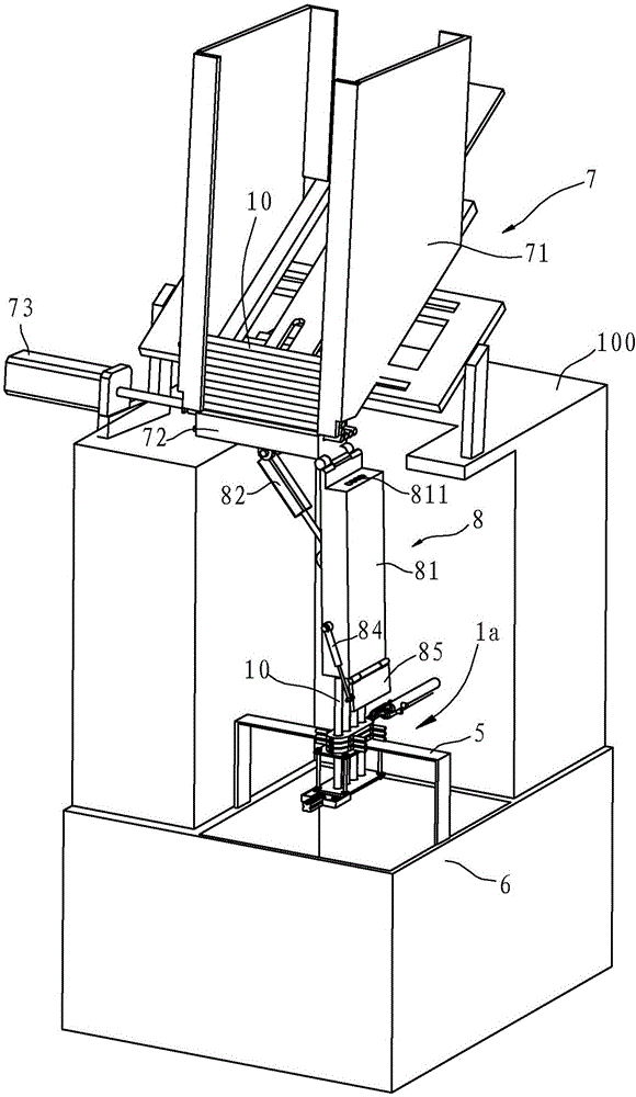
[0036] Example 1, such as figure 1 As shown, the shaft automatic quenching device in this embodiment includes a working table 100, a feeding mechanism 7, a collecting box 6, a support frame 5, a quenching mechanism 1a, and a high-frequency induction heating machine 2a (see Figure 9 ), steering assembly 8 and controller 101, feeding mechanism 7 is located on the work surface 100, and can output the workpiece horizontally and horizontally; the collection box 6 is located below the work surface 100 and has an upper port, and the support frame 5 is located on on the upper port of box 6.

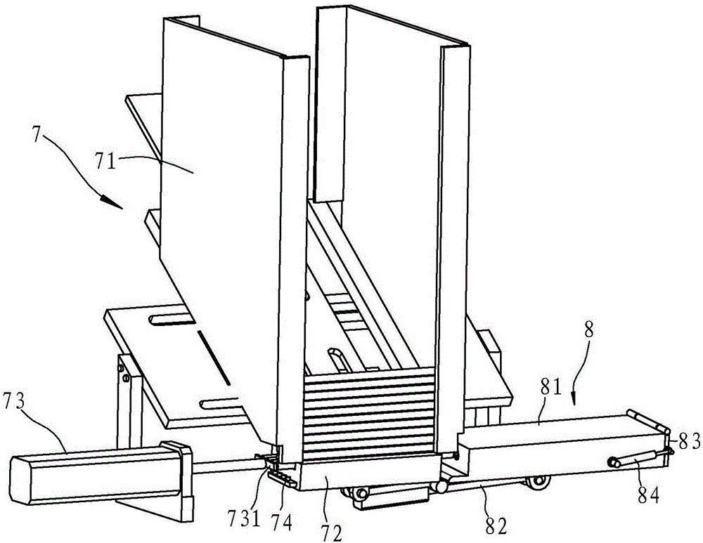
[0037] Such as figure 2 and Figure 4 As shown, the feeding mechanism 7 includes a feeding box 71, a feeding chute 72, a feeding cylinder 73 and a material limiting cylinder 75. The bottom surface of the feeding box 71 is an inclined surface inclined from top to bottom, and the feeding chute 72 is located on the feeding box 71. On the discharge port at the bottom, the feeding cylinder 73 is ...

Embodiment 2

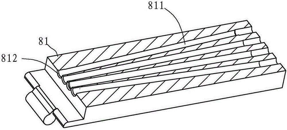
[0046] Example 2, such as Figure 10 and Figure 11 As shown, the bottom of the feeding trough 72 in this embodiment is provided with an insertion hole, and the work surface 100 is provided with a guide assembly 9, which includes a guide cylinder 91 and an insert plate 92, and the insert plate 92 is located on the guide cylinder 91. At the power output end, the front end of the insertion plate 92 has a plurality of guide teeth 93 that are arranged at intervals and can increase the gap between the workpieces. The guide cylinder 91 can drive the insertion plate 92 to move close to the feeding groove 72, so that the guide teeth 93 pass through the insertion hole 721 And protrude upwards from the bottom of feeding chute 72, as Figure 12 As shown, the channels in the steering block 81 are arranged in parallel. Before being sent into the steering block 81 , the gap between the workpieces is enlarged in advance through the function of the guide assembly 9 , so as to facilitate sub...

Embodiment 3

[0047] Example 3, such as Figure 13 As shown, the front end of the feed chute 72 in this embodiment is extended with a guide portion 72a, so that the length of the feed chute 72 is greater than the length of the workpiece 10, and the upper end surface of the guide portion 72a has a plurality of intervals and can be arranged between the workpieces 10. Guide block 72b with increased clearance. The passages 811 in the steering block 81 are arranged in parallel. Before being sent into the steering block 81, the gap between the workpieces is enlarged in advance through the action of the guide block 72b on the guide part 72a, so as to facilitate subsequent entry into the inductor 2 for quenching. Refer to Example 1 for other structures.


PUM


Abstract

An automatic shaft quenching device is characterized by comprising a working face, a feeding mechanism, an aggregating box, a support frame, a quenching mechanism, a high-frequency induction heater, a steering component and a controller, wherein the feeding mechanism can horizontally output workpieces; the steering component comprises a steering block, a steering cylinder, a cover plate and a plate pushing cylinder; one end of the steering block is hinged to one side of the feeding mechanism; channels used for accommodating the workpieces and allowing the workpieces to pass through are arranged in the steering block; the feeding ends of the channels are connected with the discharging end of the feeding mechanism; and after the steering block rotates by 90 degrees, the discharging ends of the channels are located right above through holes of an inductor. Compared with the prior art, the automatic shaft quenching device has the following advantages, the integral structure is simple, simultaneous feeding, steering, quenching, cooling and discharging are automatically realized by the controller, the quenching efficiency is improved, the labor intensity is greatly lowered, and potential safety hazards are reduced.

Description

technical field [0001] The invention relates to a quenching device, which is suitable for quenching treatment of shafts. Background technique [0002] The purpose of quenching is to transform supercooled austenite into martensite or bainite to obtain martensite or bainite structure, and then cooperate with tempering at different temperatures to greatly improve the strength, hardness and wear resistance of the steel. properties, fatigue strength and toughness, etc., so as to meet the different requirements of various mechanical parts and tools. Quenching can also be used to meet the special physical and chemical properties of some special steel materials such as ferromagnetism and corrosion resistance. [0003] At present, high-frequency quenching equipment (such as high-frequency induction heating machine tools) is widely used in shaft quenching devices. The principle of high-frequency quenching treatment is to use high-frequency quenching equipment to input medium-frequenc...

Claims


Application Information

Patent Timeline
Patent Type & Authority Applications(China)
IPC IPC(8): C21D9/28C21D1/62
CPCC21D1/62C21D9/28
Inventor 贝国生
Owner NINGBO VISTART INTELLIGENT TECH
Why Eureka
Try Eureka