
Foam flooding physical simulation device and foam flooding physical simulation method

A technology of physical simulation and foam flooding, which is used in earth-moving drilling, fluid production, wellbore/well components, etc. It can solve the problem of inability to realize real-time mixing of displacement medium, inability to ensure liquid uniformity, and poor back pressure control accuracy. problems, to achieve the effect of high control accuracy and automation, ensuring continuity and stability, and smooth operation of the device

Active Publication Date: 2016-11-16
PETROCHINA CO LTD +1
View PDF6 Cites 21 Cited by
  • Summary
  • Abstract
  • Description
  • Claims
  • Application Information

AI Technical Summary

Problems solved by technology

This device can carry out a variety of simulation experiments, but it has the following deficiencies in the physical simulation experiments of foam flooding: the high-pressure gas injected into the foam generation device does not have precise control of the injection volume and injection pressure, and the accuracy is poor; the device cannot realize flooding. Real-time stirring for the medium (foaming agent) solution itself, which cannot guarantee the uniformity of the liquid; the back pressure control accuracy is poor, and the degree of automation is low

Method used


Image

  • Foam flooding physical simulation device and foam flooding physical simulation method

Examples


Embodiment Construction

[0050] The foam flooding physical simulation device and method of the present invention will be described in detail below in conjunction with the accompanying drawings and specific embodiments.

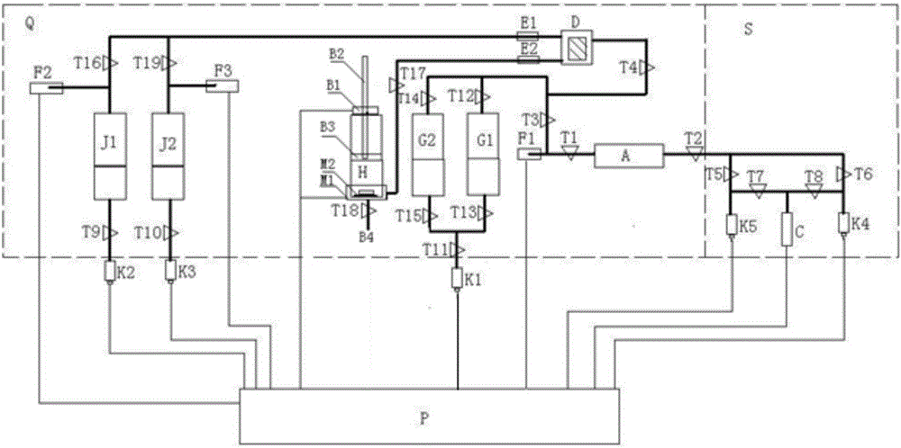
[0051] like figure 1 As shown, the embodiment of the foam flooding physical simulation device of the present invention is a kind of foam flooding physical simulation device used in the laboratory environment (the thick line represents the physical pipeline connection, and the thin line represents the electrical connection), including The model part of the reservoir, the injection part of injecting crude oil or high-pressure displacement medium (foam or water) into the model part, and the effluent collection part of collecting the effluent of the model part.

[0052] The model part in this embodiment is the core holder A, which belongs to the prior art, and it is used to make core samples of different oil levels and as a container for placing samples. It has an inlet connected to the i...


PUM


Abstract

The invention provides a foam flooding physical simulation device and a foam flooding physical simulation method. The device comprises a model part, an injecting part and an outflow liquid collecting part, wherein the model part is used for simulating an oil reservoir, the injecting part is used for injecting crude oil or a high-pressure displacing medium into the model part, and the outflow liquid collecting part is used for collecting outflow liquid from the model part; the injecting part comprises a gas piston container / gas piston containers (J1 or / and J2), a liquid piston container and a foam generating device, wherein the gas piston container / gas piston containers (J1 or / and J2) is / are used for storing a gas medium, the liquid piston container is used for storing foaming solution, and the foam generating device is used for producing foam by matching with the liquid piston container and constant-pressure and constant-speed pumps (K2 and K3); and the bottom part of the liquid piston container is provided with a magnetic stirring device and a magnetic rod. According to the foam flooding physical simulation device and the foam flooding physical simulation method provided by the invention, accurate control over injection rate and injection pressure is performed on high-pressure gas by adopting the constant-pressure and constant-speed pumps, so that accuracy is high, and the foam flooding physical simulation device is stable to work; the lower part of the liquid piston container is equipped with the magnetic stirring device, and liquid outflows from the side face of the lower part of the liquid piston container, so that the injected liquid is enabled to be uniform, and meanwhile, precipitates can be prevented from entering a core holder.

Description

technical field [0001] The invention belongs to the field of petroleum engineering and technology, and relates to a physical simulation device and method for oil displacement research in oil recovery technology, in particular to a foam flooding physical simulation device and method suitable for physical simulation evaluation experiments in tertiary oil recovery chambers. Background technique [0002] Petroleum is a non-renewable energy source, and economically and effectively developing existing oil fields is an eternal (important) subject. Water flooding can increase the recovery rate by 1 / 3-1 / 5. All major oil fields in my country are in the late stage of water flooding, but more than half of the geological reserves of oil still remain underground. Effective tertiary oil recovery technology is needed. Foam flooding has The main reason for profile control and oil displacement lies in the seepage characteristics of foam in porous media, that is, the effect of foam blocking lar...

Claims


Application Information

Patent Timeline
IPC IPC(8): E21B43/16
CPCE21B43/166
Inventor 刘宏生韩培慧陈广宇孙刚姜彬王景芹吕昌森郭松林崔长玉潘峰
Owner PETROCHINA CO LTD
Learn More