Micro heat pipe array board phase-change heat storage and release method and system

A phase change heat storage and micro heat pipe technology, applied in the field of high-efficiency phase change energy storage systems, can solve the problems of heating facilities occupying floor space, poor thermal conductivity of phase change materials, and unsatisfactory heat storage and release effects, etc. Heat transfer mode, stable performance, heat storage and fast heat extraction

Inactive Publication Date: 2016-11-16
赵耀华
View PDF2 Cites 4 Cited by
  • Summary
  • Abstract
  • Description
  • Claims
  • Application Information

AI Technical Summary

Problems solved by technology

[0004] The purpose of the present invention is to provide a micro-heat pipe array plate phase-change heat storage system, which can effectively solve the problem of large volume of heat accumulator, large pipeline resistance, high manufacturing cost, especially Due to the poor thermal conductivity and fluidity of phase change materials, the thermal resistance between the heat storage and discharge circuit is extremely large, the heat storage and discharge effect is not ideal, and

Method used


Image

  • Micro heat pipe array board phase-change heat storage and release method and system
  • Micro heat pipe array board phase-change heat storage and release method and system
  • Micro heat pipe array board phase-change heat storage and release method and system

Examples


Embodiment 1

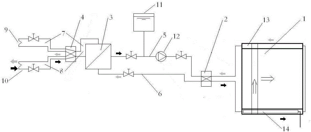
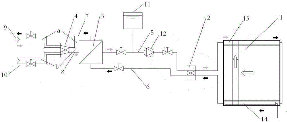
[0050] The heating end of this embodiment is a hot water heat exchange type. Whole by figure 1 and figure 2 As shown, it includes the heat accumulator 1 of the micro heat pipe array plate, the heat exchanger 3, and the pipeline connecting the user side 9, the heat source 10, the heat exchanger 3 and the heat accumulator 1, and the first four-way for switching the pipeline connection relationship The valve 2 and the second four-way valve 4 , the user side 9 and the heat source 10 exchange heat with the heat accumulator 1 through the heat exchanger 3 .

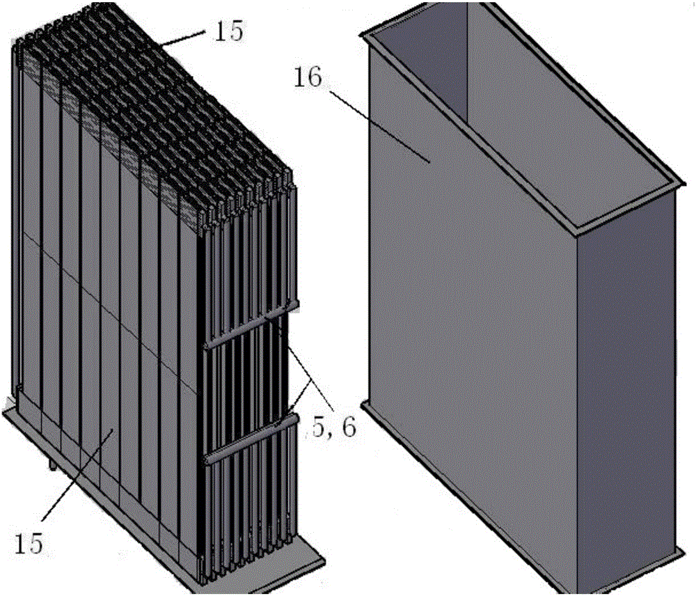
[0051] The heat accumulator 1 is a rectangular container of 1.1×1.6×0.4 as a whole, and the outer shell 16 is a rectangular container made of aluminum plate and polyurethane foam for heat preservation, and its interior is formed by a 10×9 array of heat storage units 15, such as image 3 , 4 shown. The heat storage unit 15 is designed based on the micro heat pipe array plate 17, a high-performance heat transfer material. Eac...

Embodiment 2

[0054] The heating end 14 of the present embodiment is electric heating and hot water mixing type, such as Figure 6 As shown, the micro heat pipe array plate 17 of the heating end 14 is wrapped with an electric heating belt 19. In the heat storage condition, the electric heating belt 19 and the heat carrier simultaneously provide heat to the heat storage section of the heat storage unit. Other structures and working principles are the same as in Embodiment 1.

Embodiment 3

[0056] The heating end 14 of the present embodiment is a single electric heating type, and only the micro heat pipe array plate 17 of the heating end 13 is embedded with a water exchange pipe, and the micro heat pipe array plate 17 of the heating end 14 has no heat exchange pipe. 17 wrapping electric heating belt 19, the structure of heating end 14 is as Figure 7 shown.

[0057] The piping structure of this embodiment is also different. Because of the single electric heating type, no heat source and heat source charging loop are required. When in the heat storage mode, the electric heating belt 19 at the heating end 14 is heated, and the working medium inside the micro heat pipe array plate 17 is heated and evaporated, and the heat is transferred from bottom to top in the form of steam, and the heat is conducted to the paraffin storage in the heat storage section. Stored in hot material. When in heating condition, such as Figure 8 As shown by the middle arrow, the micro-...


PUM


Abstract

The invention provides a micro heat pipe array board phase-change heat storage and release method and system. A micro heat pipe array board is arranged in a phase-change heat storage material, and heat conduction and heat exchange are directly carried out between the surrounding phase-change heat storage material and the micro heat pipe array board. Part of the surface of the micro heat pipe array board carries out heat exchange through a heat storage heat exchanger or a heat release heat exchanger, so that rapid heat storage and heat release are carried out on the phase-change heat storage material through direct heating and a cold source circuit or through a hot source circuit and the cold source circuit. The problems that a heat storage device improved from an existing coiled pipe type heat exchanger is large in size, large in pipeline resistance and high in manufacturing cost, and a phase-change material is poor in heat conduction performance and flowing property, so that heat resistance with a heat storage and release circuit is too high, the heat storage and release effects are not ideal, and heat storage can be not achieved through direct electrical heating are solved. Heat storage and heat release with low temperature difference and large power are realized, serial-connection and parallel-connection assembling can be carried out conveniently, and therefore heat storage integrated products on various scales are formed.

Description

technical field [0001] The invention relates to an efficient heat storage, release and exchange system, in particular to an efficient phase change energy storage system. Background technique [0002] Today in the 21st century, the utilization and development of energy has become a global hotspot, and the full utilization of energy has become the research direction of all walks of life. Energy saving and improving energy utilization are currently the hottest topics. In order to reduce carbon emissions and protect the environment, improving energy utilization has become an important issue that the international community needs to solve. Among them, the development and utilization of energy storage technology is a key means to improve energy utilization. It is mainly used in solar thermal storage, electric power "Moving peaks and filling valleys", industrial waste heat and waste heat recovery and other fields. [0003] Due to its advantages of high heat storage density, small...

Claims


Application Information

Patent Timeline
IPC IPC(8): F28D20/02F24H7/02
CPCF24H7/0208F28D20/021Y02E60/14
Inventor 赵耀华刁彦华张楷荣
Owner 赵耀华
Why Eureka
Try Eureka