Geometric correction method of airborne imaging hyperspectrum of unmanned aerial vehicle

A technology for geometric correction and unmanned aerial vehicle, applied in the field of image processing, can solve the problems of difficult polynomial correction geometric fine correction, low-precision POS position sensor, application limitations, etc., to achieve the effect of improving the accuracy of POS information

Active Publication Date: 2016-11-16
天岸马科技(黑龙江)有限公司
View PDF4 Cites 27 Cited by
  • Summary
  • Abstract
  • Description
  • Claims
  • Application Information

AI Technical Summary

Problems solved by technology

[0004] The load of the UAV is low, the stability of the platform is poor, and it is easily affected by airflow and wind speed. However, most hyperspectral imaging adopts the push-broom method, which makes the hyperspectral imaging affected by the attitude of the platform and has a large geometric distortion.
Subsequent geometric correction requires high-precision POS data, but due to the low load of the drone, it is impossible to carry high-precision POS equipment and other equipment
It has caused great difficulties to the practical application of UAV hyperspectral imaging
[0005] The currently used UAV geometric correction method generally simply uses ground control points for polynomial correction, but this method has high requirements for POS accuracy, and the accuracy is greatly affected by the control points
Some people use the frame camera to match and correct the hyperspectral image. However, due to the load of the drone, carrying the frame camera undoubtedly increases the cost and has certain limitations in application.
[0006] Existing low-cost small UAVs are only loaded with low-precision POS position sensors and push-broom hyperspectral imagers. Due to the influence of wind, the images obtained by correcting only based on POS data deviate too much from the actual ones. The distortion is still large, and it is difficult to perform geometric fine correction through polynomial correction, which cannot meet the actual use requirements

Method used


Image

  • Geometric correction method of airborne imaging hyperspectrum of unmanned aerial vehicle
  • Geometric correction method of airborne imaging hyperspectrum of unmanned aerial vehicle
  • Geometric correction method of airborne imaging hyperspectrum of unmanned aerial vehicle

Examples


specific Embodiment approach 1

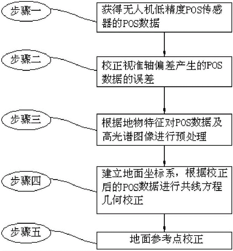
[0020] The UAV airborne imaging hyperspectral geometric correction method in this embodiment combines figure 1 As shown, the method is realized through the following steps:

[0021] Step 1. Obtain the POS data of the UAV’s low-precision POS sensor: pitch angle Φ, roll angle Ω, azimuth Ψ, flying height h, and obtain the UAV’s GPS information at the same time;

[0022] Step 2, correcting the error of the POS data generated by the deviation of the collimation axis;

[0023] Step 3. Preprocessing the POS data and the hyperspectral image according to the ground features;

[0024] Step 4, establish a ground coordinate system, and perform geometric correction of collinear equations according to the corrected POS data;

[0025] Step five, ground reference point calibration.

specific Embodiment approach 2

[0026] The difference from the specific embodiment 1 is that in the UAV airborne imaging hyperspectral geometric correction method of this embodiment, the process of correcting the POS data error caused by the deviation of the collimation axis described in step 2 is as follows:

[0027] Step 21, using the standard calibration field to obtain accurate position information of the standard reference object;

[0028] Step two and two, set the collimation axis deviation as (ex, ey, ez), and the POS data as (Φ, Ω, Ψ), then the orthogonal transformation matrix R formed by the image attitude angle is expressed as:

[0029] R = R B L ( Φ , Ω , Ψ ) R P B ( e x , e y , e...

specific Embodiment approach 3

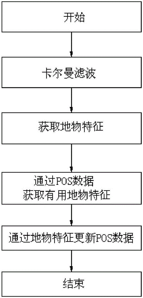
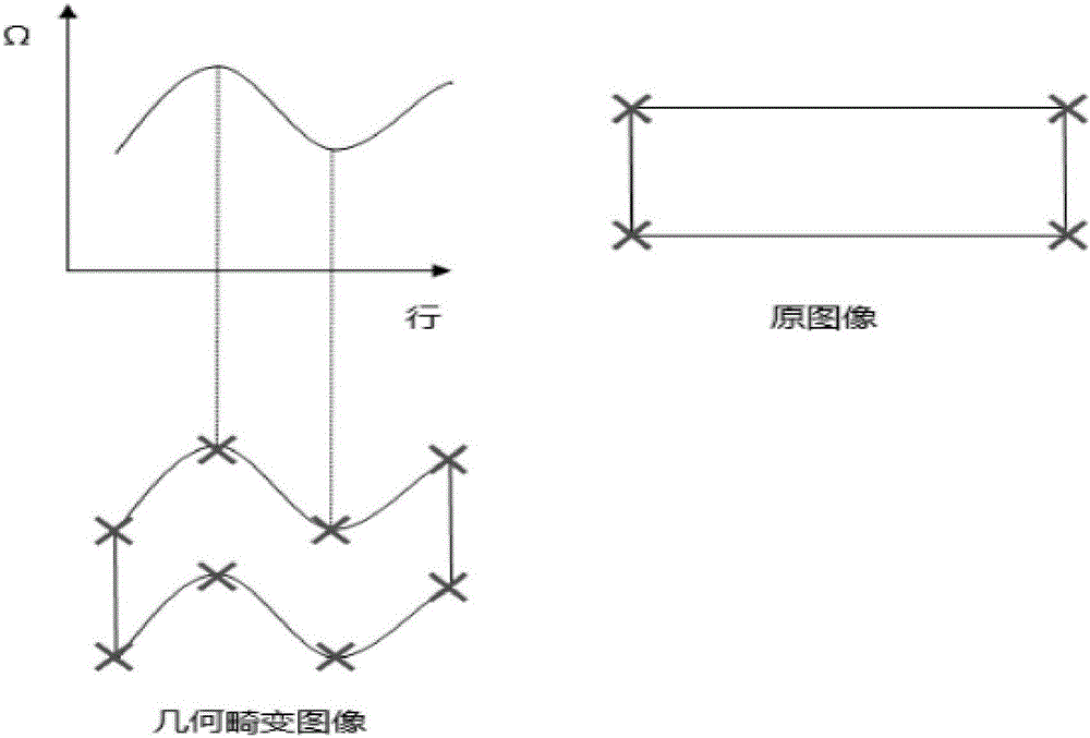
[0039] The difference from the specific embodiment 1 or 2 is that in the UAV airborne imaging hyperspectral geometric correction method of this embodiment, the process of preprocessing the POS data and the hyperspectral image according to the characteristics of the ground features described in step 3 is, because The accuracy of the POS attitude data is very low, resulting in large distortion of the ground objects. After direct correction, the distortion of the ground objects is difficult to recover, so the following processing is performed on the POS attitude data, see figure 2 :

[0040] Step 31: Carry out Kalman filtering on the POS data, and perform differential correction on the GPS information; then according to the latitude and longitude information

[0041] Calculate the distance between the abscissa and ordinate of the offset of the scan center relative to the initial scan center, and convert the unit into meters;.

[0042] Step 32: Obtain hyperspectral image corner ...


PUM


Abstract

The invention discloses a geometric correction method of an airborne imaging hyperspectrum of an unmanned aerial vehicle. At present, an image obtained according to POS (Positioning and Orientation System) data exhibits an overlarge deviation with practicality, and the point, line and surface distortion of scenery is large and is difficult in geometric fine correction through polynomial correction. The method comprises the following steps: collecting the position gesture information of a low-precision POS sensor of a current unmanned aerial vehicle to correct a collimation axis error; according to the angular point and outline information of ground object characteristics, preprocessing the POS data to obtain corresponding elements of exterior orientation; carrying out collinearity equation correction; and through a ground correction point, carrying out polynomial correction. By use of the geometric correction method, a relationship between natural ground object characteristics and the own error of the sensor is considered, correction accuracy is improved, the aerial photography low-precision POS data of the unmanned aerial vehicle is optimized, the aerial photography image of the unmanned aerial vehicle can be accurately corrected only by carrying the low-precision POS sensor and a hyperspectral imager, and technical support is provided for the wide application of the current low-cost imaging hyperspectrum of an unmanned aerial vehicle.

Description

technical field [0001] The present invention relates to a technical field of image processing, in particular to a hyperspectral geometric correction method for UAV airborne imaging. Background technique [0002] In recent years, the spatial resolution and spectral resolution of imaging hyperspectral have been getting higher and higher, which has played a great role in various fields such as agricultural automation and urban planning, and has great development potential. At present, the collection of hyperspectral images mainly relies on satellites. The orbit of the satellite platform is relatively fixed, and images at a fixed time can only be obtained, and information cannot be collected in real time on the spot. It is greatly affected by the weather and other shortcomings. It is difficult to meet the current industrial and agricultural requirements for high Spectral image temporal resolution requirements. [0003] UAVs have the advantages of high real-time performance, ada...

Claims


Application Information

Patent Timeline
Patent Type & Authority Applications(China)
IPC IPC(8): G06T5/00
CPCG06T5/006G06T2207/10016G06T2207/30181
Inventor 谷延锋王腾飞
Owner 天岸马科技(黑龙江)有限公司
Why Eureka
Try Eureka