Energy-saving sludge drying process and device

A sludge drying and sludge technology, applied in the direction of dehydration/drying/concentrated sludge treatment, etc., can solve the problems of non-compliance with energy conservation and emission reduction policies, large heat energy consumption, poor technical and economical conditions, etc., to ensure long-term stability , Reduce system cost and reduce burden

Inactive Publication Date: 2016-11-23
CEEP CO LTD
View PDF3 Cites 15 Cited by
  • Summary
  • Abstract
  • Description
  • Claims
  • Application Information

AI Technical Summary

Problems solved by technology

[0003] At present, sludge drying treatment methods and devices mainly include rotary kiln hot air drying, belt hot air drying, fluidized bed hot air drying, and paddle drying, but these traditional processes consume a lot of heat energy and are relatively poor in technology and economy.
Does not meet the requirements of the national energy conservation and emission reduction policies and guidelines
Especially for drying systems that use steam as a heat source, the temperature of the condensed water after the steam releases heat is 95-100°C. Whether the condensed water is discharged or recycled, the temperature must be lowered to below 45°C. It also needs cooling water all the way for cooling, thus causing repeated waste of energy

Method used


Image

  • Energy-saving sludge drying process and device

Examples


Embodiment Construction

[0014] In order to better understand the technical content of the present invention, specific embodiments are given together with the attached drawings for description as follows.

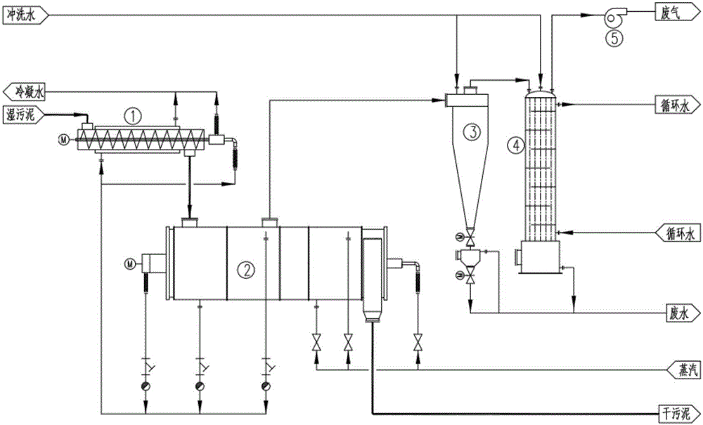
[0015] figure 1 It is a process flow chart of the energy-saving sludge drying process of the present invention. Such as figure 1 As shown, sludge preheater (1), indirect heating sludge dryer (2), cyclone dust collector (3), waste gas condenser (4) and waste gas induced draft fan (5).

[0016] The steam is sent to the indirect heating sludge dryer (2) through the pipe, and the condensed water of the steam after heat release still contains a certain amount of heat, and the condensed water is sent to the sludge preheater (1) through the pipe to release the remaining heat again , this part of the remaining heat can preheat the sludge to be dried, reducing the heat consumption of the sludge in the indirectly heated sludge dryer (2);

[0017] The wet sludge is transported to the sludge preheater (1) t...


PUM


Abstract

Provided is an energy-saving sludge drying method. A sludge preheater, an indirect heating sludge dryer, a cyclone dust collector, a waste gas condenser and a waste gas draught fan are adopted. Steam is conveyed into the indirect heating sludge dryer (2) through a pipeline, steam condensate generated after the steam releases heat in the indirect heating sludge dryer contains excess heat, the steam condensate is conveyed into the sludge preheater (1) through a pipeline, the excess heat is released again, and sludge to be dried is preheated with the excess heat. The wet sludge is conveyed into the sludge preheater (1) through a pipeline and preheated through the sludge preheater, and the temperature of the sludge rises to 50 DEG C or above; the sludge is heated in the indirect heating sludge dryer (2), and moisture and other volatilizable components in the sludge are heated and generate gas. A material accumulation hopper is arranged below the cyclone dust collector, the hopper and a dust collector body are provided with normally open isolation valves, an outlet in the lower portion is provided with a normally closed sewage discharge isolation valve, the volume of the waste gas is reduced after the waste gas is changed into a liquid state from a gaseous state, and then the waste gas is discharged through the waste gas draught fan.

Description

technical field [0001] The invention relates to the technical field of sludge treatment, and in particular relates to an energy-saving sludge drying process and device. Background technique [0002] With the development of the economy and the improvement of people's living standards, the process of urbanization is accelerating, the amount of industrial sewage and domestic sewage is increasing, and the amount of sludge generated is also increasing. At the same time, my country's industrial field is developing rapidly. The sludge discharge of pharmaceutical and chemical enterprises is increasing rapidly, and the resulting environmental pollution is becoming more and more serious. For this reason, the state strongly supports sludge reduction and incineration technology, among which drying technology has been greatly developed and applied. [0003] At present, sludge drying treatment methods and devices mainly include rotary kiln hot air drying, belt hot air drying, fluidized be...

Claims


Application Information

Patent Timeline
Patent Type & Authority Applications(China)
IPC IPC(8): C02F11/12
CPCC02F11/12
Inventor 王世兴秦正兵徐锐胡诚
Owner CEEP CO LTD
Why Eureka
Try Eureka