Natural gas distribution type energy supply system of hospital

A distributed, natural gas technology, applied in the fuel system, exhaust gas treatment, gaseous engine fuel, etc., can solve the problems affecting the promotion and application of distributed energy, achieve good application prospects and promotion value, efficient cascade utilization, load change adaptable effect

Inactive Publication Date: 2016-11-23
HUADIAN ELECTRIC POWER SCI INST CO LTD
View PDF9 Cites 8 Cited by
  • Summary
  • Abstract
  • Description
  • Claims
  • Application Information

AI Technical Summary

Problems solved by technology

[0009] At present, there is no efficient and feasible distributed energy supply system integration scheme that can provide various energy sources such as electricity, hot water, and chilled water, and can me

Method used


Image

  • Natural gas distribution type energy supply system of hospital
  • Natural gas distribution type energy supply system of hospital

Examples


Embodiment 1

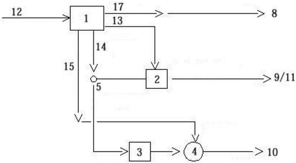
[0030] Such as figure 1 As shown, this embodiment is composed of an internal combustion engine 1, a flue gas hot water type lithium bromide cooling and heating dual-purpose unit 2, a flue gas hot water heat exchanger 3, a hot water storage tank 4 and a three-way regulating valve 5.

[0031] The internal combustion engine 1 is connected with a natural gas pipeline 12, a cylinder jacket water pipeline 13, a flue gas pipeline 14 and an intercooling water pipeline 15. The cylinder jacket water pipeline 13 is also connected with the flue gas hot water type lithium bromide refrigeration and heating dual-purpose unit 2, and the flue gas pipeline 14 It is also connected to the flue gas hot water type lithium bromide refrigeration and heating dual-purpose unit 2 and the flue gas hot water heat exchanger 3 respectively through the three-way regulating valve 5, and the flue gas hot water heat exchanger 3 is connected to the hot water storage tank 4. The cold water pipeline 15 is also con...

Embodiment 2

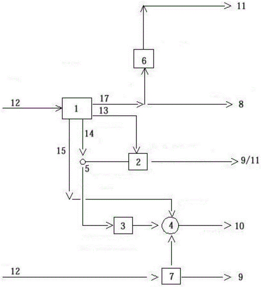
[0035] Such as figure 2 As shown, the present embodiment is similar to embodiment 1, and its difference only lies in:

[0036] 1. It also includes an electric refrigerator 6 and a gas boiler 7, the internal combustion engine 1 is connected to the electric refrigerator 6, and the gas boiler 7 is connected to the hot water storage tank 4 and the natural gas pipeline 12 respectively.

[0037] 2. The electric refrigerator 6 is connected to the air-conditioning and cooling equipment 11 of the hospital, and the gas boiler 7 is connected to the air-conditioning and heating equipment 9 of the hospital.

[0038] 3. The hot water storage tank 4 is also provided with a thermal insulation device.

[0039]The present invention adopts internal combustion engine 1 power generation technology, lithium bromide absorption refrigeration and heating technology, waste heat recovery and utilization technology, energy storage technology, distributed energy integration technology, etc. The water h...


PUM


Abstract

The invention relates to a natural gas distribution type energy supply system of a hospital. The system comprises an internal combustion engine, a smoke and hot water type lithium bromide refrigerating and heating dual unit, a smoke and hot water heat exchanger, a hot water storage tank and a three-way regulating valve. The internal combustion engine is connected with a natural gas pipeline, a jacket water pipeline, a smoke pipeline and an intercooling water pipeline. The jacket water pipeline is further connected with the smoke and hot water type lithium bromide refrigerating and heating dual unit. The smoke pipeline is further connected with the smoke and hot water type lithium bromide refrigerating and heating dual unit and the smoke and hot water heat exchanger through the three-way regulating valve. The smoke and hot water heat exchanger is connected with the hot water storage tank. The intercooling water pipeline is further connected with the hot water storage tank. According to the natural gas distribution type energy supply system, different quantity demands of the hospital for sanitary hot water at different times are met through the hot water storage tank, and the problem that system operation is unstable due to great hot water load fluctuation is solved.

Description

technical field [0001] The invention relates to an energy supply system, in particular to a hospital natural gas distributed energy supply system. Background technique [0002] Natural gas distributed energy refers to the use of natural gas as fuel to realize the cascade utilization of energy through combined cooling, heating and power supply, etc. The comprehensive energy utilization efficiency is above 70%, and the modern energy supply method that realizes energy supply near the load center is natural gas. An important way to use it efficiently. This system is developed on the basis of the cogeneration system and is mainly used to meet various energy needs. It is a further expansion and expansion of the traditional cogeneration system in terms of application scale and application occasions. [0003] Distributed energy is a brand-new, efficient and environmentally friendly energy utilization method for primary energy. On the one hand, it comprehensively solves energy conv...

Claims


Application Information

Patent Timeline
IPC IPC(8): F02B43/10F02B63/04F02G5/02F02G5/04
CPCF02B43/10F02B63/04F02B2043/103F02B2201/04F02G5/02F02G5/04F02G2260/00Y02E20/14Y02T10/12Y02T10/30
Inventor 童航孙亮曹玺彬马洪涛
Owner HUADIAN ELECTRIC POWER SCI INST CO LTD
Why Eureka
Try Eureka