
Ground driving device with hydraulic, speed-limiting and temperature-control reverse rotation preventing function

A driving device, anti-reverse technology, applied to pump devices, brake types, machines/engines, etc., can solve problems such as accidents, effect decline, personal accidents, etc.

Active Publication Date: 2016-11-23
FUTAI GASOLINEEUM MACHINOFACTURE LIAONING PROV
View PDF8 Cites 3 Cited by
  • Summary
  • Abstract
  • Description
  • Claims
  • Application Information

AI Technical Summary

Problems solved by technology

[0002] When the screw pump oil production system is shut down, the reverse potential energy stored in the sucker rod is released instantly, which will drive the belt pulley and other devices to run in reverse at high speed, which will easily cause damage to the transmission device or personal accidents
Existing screw pump drive devices mostly use hydraulic brakes. The disadvantage is that if the parts are damaged or oil leaks, the effect will drop significantly or even fail, and accidents will occur, which will pose a great safety hazard.

Method used


Image

  • Ground driving device with hydraulic, speed-limiting and temperature-control reverse rotation preventing function
  • Ground driving device with hydraulic, speed-limiting and temperature-control reverse rotation preventing function
  • Ground driving device with hydraulic, speed-limiting and temperature-control reverse rotation preventing function

Examples


Embodiment Construction

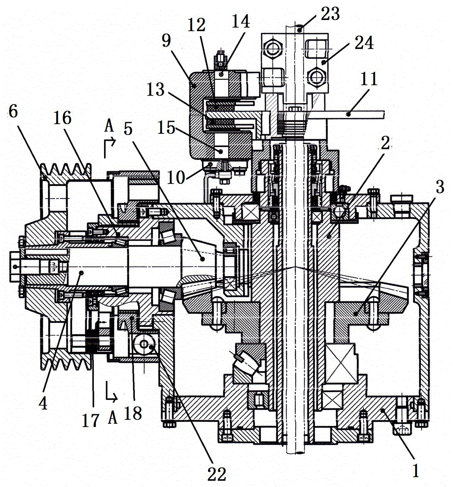
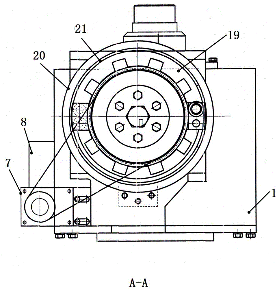
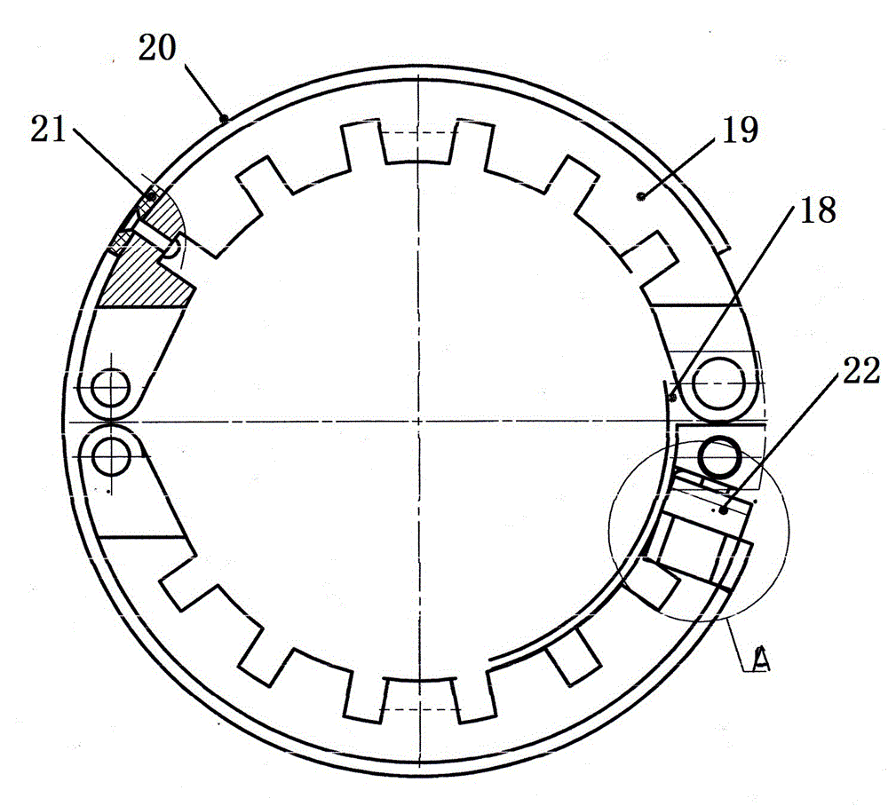
[0011] refer to figure 1 —4, it includes reduction box 1, and vertical shaft 2 is contained in the reduction box, and gear 3 is arranged on the vertical shaft, and bevel gear 5 is arranged on the main shaft 4 that stretches into the reduction box, and the bevel gear on the main shaft and the gear on the vertical shaft meshing, there is a large pulley 6 on the main shaft, the gear pump 7 is installed on the pump seat on the reduction box, the hydraulic oil tank 8 is installed on the top of the gear pump, the oil outlet of the hydraulic oil tank is connected with the oil inlet of the gear pump, and the gear pump The oil outlet has an oil pipe connected to the oil inlet of the brake caliper 9, the brake caliper is fixed on the brake seat 10, the brake seat is fixed on the upper cover of the reduction box, the brake disc 11 is installed on the top of the vertical shaft, and the brake There is an upper friction block 12 above the disc, and a lower friction block 13 below the brake ...


PUM


Abstract

The invention provides a ground driving device with a hydraulic, speed-limiting and temperature-control reverse rotation preventing function and relates to a screw pump ground driving device used in an oil field. The ground driving device with the hydraulic, speed-limiting and temperature-control reverse rotation preventing function is designed mainly for solving the problem that an existing screw pump driving device has potential safety hazard. The ground driving device with the hydraulic, speed-limiting and temperature-control reverse rotation preventing function comprises a reduction gearbox, a vertical shaft, a big belt wheel, a gear pump and a hydraulic oil tank. The gear pump is connected with a brake caliper through an oil pipe. A brake disc is mounted at the top of the vertical shaft. An upper friction block and a lower friction block are mounted on the brake caliper. The brake caliper communicates with an upper hydraulic cavity and a lower hydraulic cavity through pipelines. A bevel gear shell of a brake hub is fixed to the reduction gearbox. A ratchet wheel sleeve of a pawl type centrifugal overrun clutch is arranged on the bevel gear shell. A brake disc is mounted on the ratchet wheel sleeve. A small belt wheel fixed to the brake disc is connected with a belt wheel on the gear pump through a belt. A pawl is mounted on the brake disc. The rear ends of two brake shoes are hinged together. The front end of one brake shoe is mounted on the brake disc. The front ends of the two brake shoes are connected through a spring. Brake pads are arranged on the brake shoes. The ground driving device with the hydraulic, speed-limiting and temperature-control reverse rotation preventing function has the advantage of being high in safety.

Description

Technical field: [0001] The present invention relates to a ground drive unit for a screw pump used in an oil field. Background technique: [0002] When the screw pump oil production system is shut down, the reverse potential energy stored in the sucker rod is released instantly, which will drive the belt pulley and other devices to run in reverse at high speed, which will easily cause damage to the transmission device or personal accidents. Existing driving devices of screw pumps mostly use hydraulic brakes. The disadvantage is that if the parts are damaged or oil leaks, the effect will drop significantly or even fail, and accidents will occur, which will pose a great safety hazard. Invention content: [0003] The technical problem to be solved by the present invention is to provide a ground drive with hydraulic pressure, speed limit, temperature control and anti-reverse functions that can still achieve braking when the components of the hydraulic brake system are damaged ...

Claims


Application Information

Patent Timeline
Patent Type & Authority Applications(China)
IPC IPC(8): F04D3/02F04D13/02F16D65/14F16D66/00F16D65/78F16D121/04
CPCF04D3/02F04D13/02F16D65/14F16D65/78F16D66/00F16D2066/001F16D2121/04
Inventor 韩全伟田澍藩
Owner FUTAI GASOLINEEUM MACHINOFACTURE LIAONING PROV
Learn More