Stepper motors for automation control

An automatic control, stepper motor technology, applied in the direction of electric components, electromechanical devices, electrical components, etc., can solve the problems of inconsistent increase of positioning datum, the formation of burrs, and the increase of resistance between the motor shaft and the bearing, so as to avoid the relative position. Changes, alignment of positioning datums, reduction of vibration and noise

Active Publication Date: 2019-08-06
JIANGSU LEILI MOTOR
View PDF9 Cites 0 Cited by
  • Summary
  • Abstract
  • Description
  • Claims
  • Application Information

AI Technical Summary

Problems solved by technology

As a result, the assembly error between the circumferential pole claws in the casing becomes larger, and the error of the inner diameter of the superimposed pole claws also increases; these errors lead to a large torque ripple during the operation of the motor, and the vibration is large and the noise is large , the output characteristics and consistency of the motor are poor, and the primary flow rate on the production line will be very poor
Since the notch of the positioning casing is made by a pair of molds, the two casings are reversely superimposed and fastened, which increases the inconsistency of the positioning reference, and even causes the middle pole plate and the coil assembly to loosen. The relative position between the pole plate, the coil assembly and the casing has changed, resulting in a difference between the actual performance and the factory performance, which seriously affects the actual use of the motor; in addition, the rotor of the existing BY series stepping motor is mainly made of UV glue. Or anaerobic adhesive, the metal bushing and the NdFeB magnetic ring, the metal bushing and the rotor shaft are bonded together to form a whole, and the metal bushing requires high processing accuracy, and the anti-rotation rib needs to be set in the axial direction , the machining process is difficult to realize; in addition, the three parts that make up the rotor are all made by gluing process, which is complex and has high requirements on the level of operators and the environment. The bonding accuracy will cause the defects of weak bonding between the parts and poor coaxiality between the outer diameter of the rotor and the rotor shaft after bonding and curing. If the overflowing glue is not cleaned up in time during the bonding process, it will cause The cured rotor has a flash phenomenon, and the flash is easily brought into the motor to form garbage, thereby blocking the rotation of the rotor, and the overflowing glue is also likely to remain on the rotor shaft, which increases the resistance between the normal working motor shaft and the bearing. Affect the pull-out torque, and cause the motor to be stuck in serious cases; these technical problems are common in motor rotor products that are bonded with glue, and there is no more reasonable way to solve this technical problem until now, resulting in BY series step-by-step The motor cannot meet the accurate positioning accuracy control requirements in the demanding patented equipment drive occasions, which limits the application of this type of product in the field of automation control

Method used


Image

  • Stepper motors for automation control
  • Stepper motors for automation control
  • Stepper motors for automation control

Examples


Embodiment Construction

[0051] In order to make the content of the present invention more clearly understood, the present invention will be further described in detail below based on specific embodiments and in conjunction with the accompanying drawings.

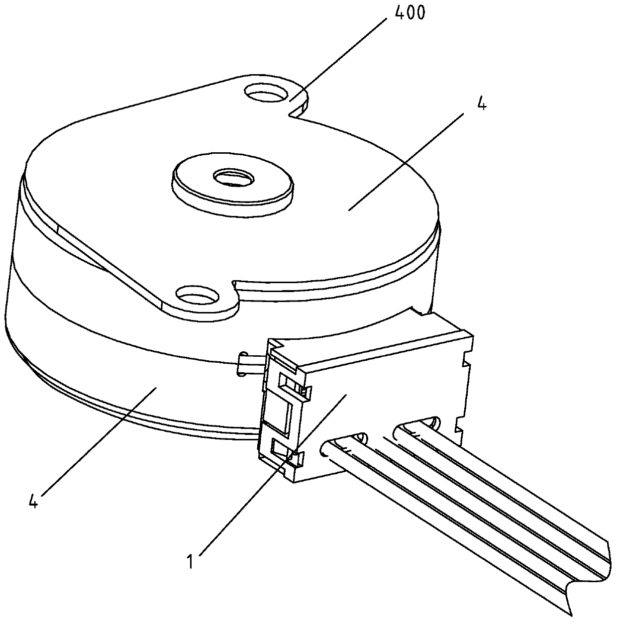
[0052] Such as Figure 1-19 As shown, a stepping motor applied to automatic control includes a rotor and a motor stator assembly, and the rotor is rotatably supported on the motor stator assembly; wherein,

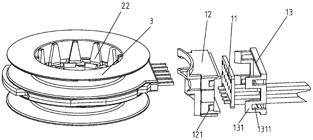
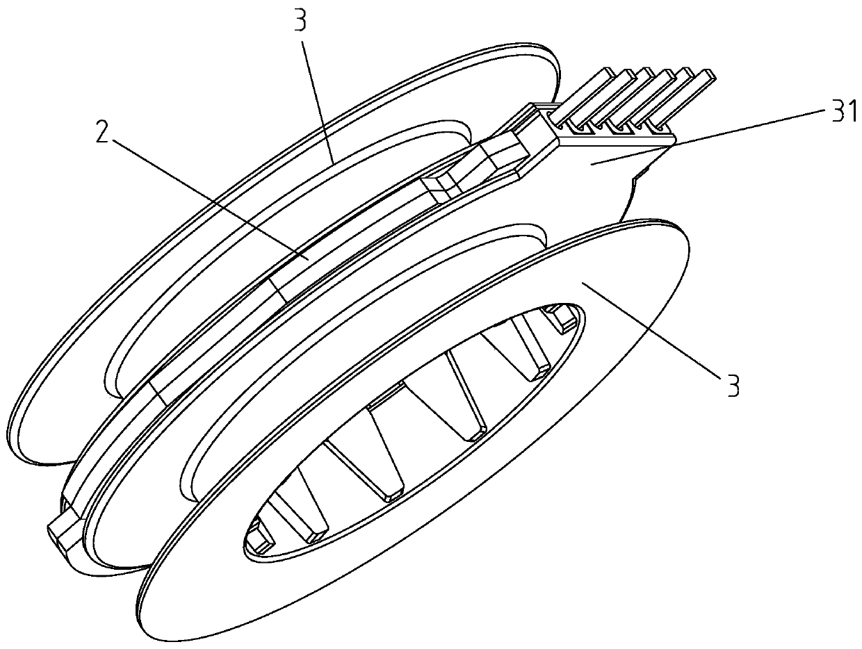
[0053] The motor stator assembly includes an outlet box 1 and two stator subassemblies assembled together, the stator subassembly includes a middle pole plate 2, a coil assembly 3 and a casing 4; one end of the casing 4 forms a casing bottom, The other end of the casing 4 is an open end, and the opening end of the casing 4 is provided with a notch 41 coaxially arranged with the rotation axis of the casing 4, and the opening end of the casing 4 is also provided with a gap 42; The middle pole plate 2 is provided with a protruding portion 21 prot...


PUM


Abstract

The invention discloses a stepping motor applied to automation control. The stepping motor comprises a rotor and a motor stator assembly, wherein the rotor is supported on the motor stator assembly rotatablely; the motor stator assembly comprises an outlet box and two stator sub-assemblies assembled together, and each stator sub-assembly comprises a middle polar plate, a coil block and a main case; a main case base is formed at one end of the main casing, the other end of the main case is opened, a seam allowance part coaxially arranged together with the rotating shaft of the main case is arranged at the opening end of the main case, and a notch is further formed in the opening end of the main case; a protruding part corresponding to the notch and protruding outward in the radial direction is arranged on the middle polar plate; the rotor comprises a magnet ring, a shaft and an injection molding body, wherein the injection molding body is arranged between the magnet ring and the shaft, so as to enable the rotating shaft and the magnet ring to be integrated by the injection molding body. According to the stepping motor provided by the invention, not only the shaft and the magnet ring are integrated through injection molding, but also the manufacturing accuracy of the rotor is improved, accumulated errors caused during stator assembly assembling are reduced, and the datum reference is kept to be consistent.

Description

technical field [0001] The invention relates to a stepping motor applied to automatic control. Background technique [0002] At present, in the existing BY series stepping motors, the stator casing, the middle pole plate and the coil assembly that constitute the stator assembly are all positioned and installed with a relatively simple stator notch. This positioning method is used to install the After the middle pole plate and the coil assembly are positioned first, then the coil assembly and the notch of the casing are positioned, and the cumulative error is relatively large. As a result, the assembly error between the circumferential pole claws in the casing becomes larger, and the error of the inner diameter of the superimposed pole claws also increases; these errors lead to a large torque ripple during the operation of the motor, and the vibration is large and the noise is large , The output characteristics and consistency of the motor are poor, and the primary flow rate...

Claims


Application Information

Patent Timeline
Patent Type & Authority Patents(China)
IPC IPC(8): H02K37/00H02K1/14H02K1/22H02K3/52H02K5/04H02K5/22
CPCH02K1/145H02K1/22H02K3/525H02K5/04H02K5/225H02K37/00H02K2213/03
Inventor 赵殿合党红关
Owner JIANGSU LEILI MOTOR
Why Eureka
Try Eureka