
Stator coil bar structure of large power generator

A technology for generator stators and stator bars, applied to the shape/style/structure of winding insulation, the shape/style/structure of winding conductors, electrical components, etc., which can solve the problem of overheating of wire bars and affecting the service life of stator bars, etc. problem, to achieve the effects of alleviating electric field concentration, good electrical contact, and homogenizing electric field distribution

Inactive Publication Date: 2016-11-30
HARBIN UNIV OF SCI & TECH +1
View PDF4 Cites 5 Cited by
  • Summary
  • Abstract
  • Description
  • Claims
  • Application Information

AI Technical Summary

Problems solved by technology

These gaps are usually filled with some insulating materials. These filling insulations only fill up the geometry of the narrow surface of the transposed bar. When the generator is running, the electric field inside the bar still has a field concentration phenomenon, which makes the local main insulation of the stator bar Under the high field strength, it will lead to local overheating of the wire rod, and the long-term operation will accelerate the electrical aging and thermal aging of the wire rod, which will affect the service life of the stator wire rod

Method used


Image

  • Stator coil bar structure of large power generator

Examples


specific Embodiment approach

[0015] Specific embodiments: below in conjunction with specific embodiment, further illustrate the present invention. It should be understood that these examples are only used to illustrate the present invention and are not intended to limit the scope of the present invention. In addition, it should be understood that after reading the content taught by the present invention, those skilled in the art can make various changes and modifications to the present invention, and these equivalent forms also fall within the scope defined by the appended claims of the present application.

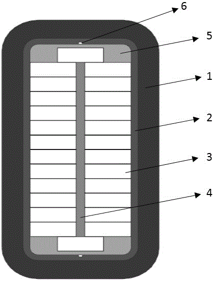
[0016] Such as figure 1 As shown, it is a schematic diagram of the structure of the stator bar according to the present invention, including a main insulating layer 1, a semiconductor tape layer 2, an electromagnetic wire row 3, an inter-row insulation 4, a semiconductor putty 5, and a bare copper wire 6. The inter-row insulation 4 is arranged in the middle of the electromagnetic wire row 3; the sem...


PUM


Abstract

The invention provides a stator coil bar structure of a large power generator. The stator coil bar structure comprises a main insulation unit, a semiconductor band, electromagnetic wires, an inter-row insulation unit, semiconductor putty and a bare copper wire. The stator coil bar structure is characterized in that the inter-row insulation unit is arranged in the middle of each electromagnetic wire; a gap generated by transposition is filled with the semiconductor putty on transposition narrow surfaces on two sides of the electromagnetic wire, and four corners of the semiconductor putty on the upper and lower narrow surfaces are rounded; and the transposition narrow surfaces on the outer side of the semiconductor putty are paved with the bare copper wire welded together with a conductor of the electromagnetic wire, and then a stranded wire of the conductor is wrapped with the semiconductor band with the same resistance range as the semiconductor putty. The stator coil bar structure has the characteristics that a conductor structure has good overall shape and a semiconductor equipotential layer is improved, so that the effects of homogenizing electric fields at the corners of the main insulation unit of the stator coil bar of the large power generator, inhibiting local discharge, reducing additional loss of the coil bar and avoiding local overheating to prolong the service life of the main insulation unit are achieved; and the unit capacity and operation reliability of the power generator are improved.

Description

technical field [0001] The invention relates to a large-scale generator stator bar structure, which can homogenize the electric field inside the transposition bar and eliminate the electric field concentration phenomenon caused by the sudden change of shape inside the bar, especially the transposition narrow surface and the four parts of the bar. The electric field concentrates at the corners. The risk of partial discharge is reduced, the electrical insulation strength of the stator bar is improved, and it belongs to the field of large-scale generator insulation research. Background technique [0002] In the production process of large generator stator bars, in order to avoid the additional loss caused by the conductor eddy current and strand circulation, the method of multi-strand wire transposition is usually used to reduce the additional loss; The bit narrow face forms many transposition gaps. These gaps are usually filled with some insulating materials. These filling i...

Claims


Application Information

Patent Timeline
Patent Type & Authority Applications(China)
IPC IPC(8): H02K3/04H02K3/34
CPCH02K3/04H02K3/34H02K2213/03
Inventor 张晓虹李文强张博伟曹铁男李瑞显
Owner HARBIN UNIV OF SCI & TECH
Learn More