Control device and method for lake water contamination
A technology of water pollution and resistance control, which is applied in the field of lake water pollution control, can solve the problems of secondary pollution of lakes, unclear resistance control mechanism and process of external resistance materials, and differences in the control process of lake water pollutants, etc., to achieve good results. The effect of blocking effect
- Summary
- Abstract
- Description
- Claims
- Application Information
AI Technical Summary
Problems solved by technology
Method used
Image

Examples
Embodiment 1
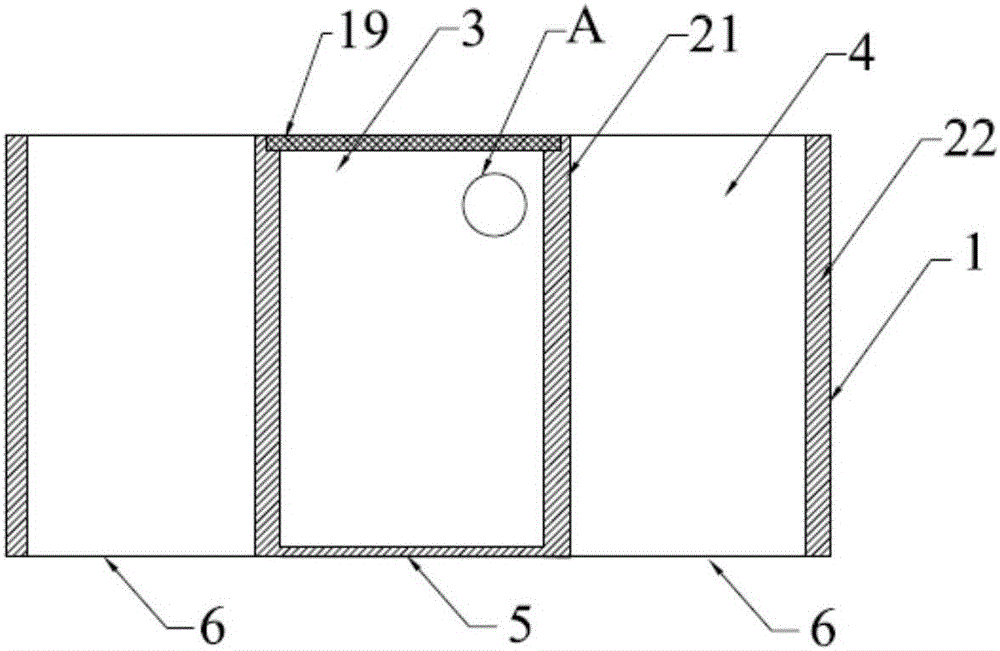
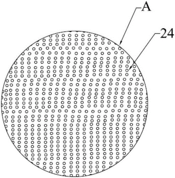
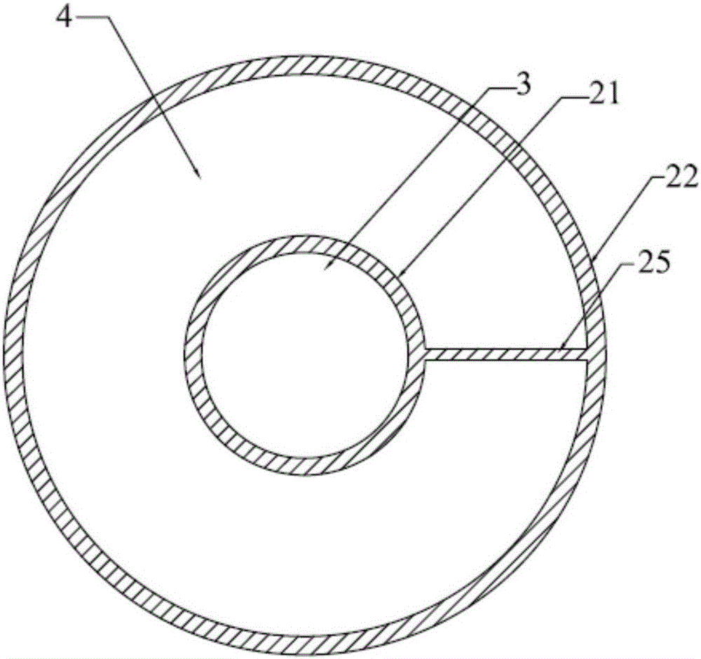
[0051] The resistance and control device used for lake water pollution provided in this embodiment is as follows: Figure 1-3 As shown, it includes: a shell 1 for inserting into the sediment at the bottom of the lake. In this embodiment, the shell 1 includes two cylindrical walls 21, 22 with different diameters. The cylinder walls 21 , 22 are arranged concentrically and nested in turn, and are fixedly connected by a fixed rod 25 in the radial direction; the top and bottom ends of the two cylindrical cylinder walls 21 , 22 are arranged flush. A cylindrical cavity is formed inside the cylindrical barrel wall 21 located on the inner side, and an annular cavity is formed between the two cylindrical barrel walls, and the cylindrical cavity and the annular cavity Adjacent in the horizontal direction; the cylindrical cavity described in this embodiment is used as a resistance control material cavity, the bottom surface 5 of the resistance control material cavity is airtightly arrange...
Embodiment 2
[0055] The resistance and control device used for lake water pollution provided in this embodiment is as follows: Figure 4 As shown, on the basis of Embodiment 1, this embodiment further adds a first sampling device, and the first sampling device includes:
[0056] The first cylindrical body 7, the first cylindrical body 7 is fixedly connected with the housing and the cylinder wall of the first cylindrical body forms an enclosure on both sides of the side wall of the cavity, and the enclosure includes Two regions on both sides of the side wall of the cavity; the first cylinder 7 is extended in the horizontal direction along the radius of the cylindrical cylinder 22 located on the outside; in this embodiment, the first cylinder 7 The cross-section of the part located in the resistance-control material chamber is fan-shaped, and the cross-section of the part of the first cylinder 7 located in the sediment chamber is elongated with constant width.
[0057] Such as Figure 5 wi...
Embodiment 3
[0064] The prevention and control device for lake water pollution provided in this embodiment includes: a shell 1 for inserting into the sediment at the bottom of the lake, and the shell 1 in this embodiment includes two cylinders with different diameters Cylindrical cylinder walls 21, 22, the two cylindrical cylinder walls 21, 22 are sequentially nested and arranged concentrically, and are fixedly connected by a fixed rod 25 in the radial direction. A cylindrical cavity is formed inside the cylindrical barrel wall 21 located on the inner side, and an annular cavity is formed between the two cylindrical barrel walls, and the cylindrical cavity and the annular cavity Adjacent in the horizontal direction; the bottom surface 5 of the cylindrical cavity in this embodiment is airtightly arranged, and the bottom surface 5 is set as a plane; a resistance control material is placed in the cylindrical cavity for use as a resistance Control material cavity 3; the top of the resistance c...
PUM
| Property | Measurement | Unit |
|---|---|---|
| Particle size | aaaaa | aaaaa |
| Particle size | aaaaa | aaaaa |
Abstract
Description
Claims
Application Information
 - R&D
- Intellectual Property
- Life Sciences
- Materials
- Tech Scout
- Unparalleled Data Quality
- Higher Quality Content
- 60% Fewer Hallucinations
Browse by: Latest US Patents, China's latest patents, Technical Efficacy Thesaurus, Application Domain, Technology Topic, Popular Technical Reports.
© 2025 PatSnap. All rights reserved.Legal|Privacy policy|Modern Slavery Act Transparency Statement|Sitemap|About US| Contact US: help@patsnap.com