Crossed roller bearing with roller path with convexity and manufacturing method thereof

A technology of a crossed roller bearing and a manufacturing method, which is applied to a crossed roller bearing with a convex raceway and its manufacturing field, can solve the problems of insufficient running accuracy and service life, reduced bearing capacity, poor machining accuracy, etc. The effect of improving operation accuracy and reliability, reducing friction torque and operating temperature rise, and improving anti-skew ability

Active Publication Date: 2016-12-07
SHANGHAI F&S BEARING TECH
View PDF8 Cites 5 Cited by
  • Summary
  • Abstract
  • Description
  • Claims
  • Application Information

AI Technical Summary

Problems solved by technology

When the scratched raceway is in contact with the working surface of another row of rollers, under the relatively high contact stress, the flexibility and stability of the bearing operation will be affected first, and at the same time, the scratches will also become early fatigue failures. root cause, affecting the reliability and life of bearing operation
[0005] Crossed roller bearings are often used in occasions where the speed is not high but the load type is complex, the load value is large, and the precision in all directions is extremely high, such as the turntable of precision machine tools, the waist and crotch of industrial robots, etc. The high running precision in all directions is conversely Bearings are required to have high radial stiffness, axial stiffness, angular stiffness or moment stiffness. In order to improve the stiffness of the bearing, crossed roller bearings often use small clearance or even negative clearance. There are many rollers inside the roller bearing, that is, there are a lot of roller-raceway contact pairs (N rollers have 4N contact pairs), so it brings about an increase in starting and running friction torque, which in turn causes As the temperature of the bearing rises, the accuracy of the bearing and the main engine will inevitably decrease as the temperature rises. In terms of service life, there are the above-mentioned deficiencies
[0006] Under heavier loads, the V-shaped raceway of the crossed roller bearing without convexity will cause the edge effect of the singular distribution of pressure at the two ends of the contact area, that is, the end of the raceway when the rollers are in contact with the raceway, and will cause As a result, pressure concentration occurs in the middle of the raceway. Since the failure of the bearing occurs at the contact part with the highest stress in the contact area, the bearing capacity of the bearing is seriously reduced, and the risk of local early fatigue failure in the contact area is very high. The anti-skewing ability of the bearing is very poor, and if there is a slight eccentric load on the outside, the bearing will have the risk of poor rotation or even sticking
[0007] In the current crossed roller bearing structure, one of the rings adopts an integral split structure, that is, the ring is fastened by two rings with one side of the raceway through connecting screws, because the two halves of the ring need to be separated before heat treatment. Manufacturing and processing, not only the processing accuracy is poor, but also the processing efficiency is low
[0008] From the point of view of the manufacturing process, the raceway of the cross roller bearing ring in the current technology is formed by the plunge grinding method. Due to the limitation of the low precision of the grinding wheel and the poor heat dissipation conditions of the grinding, the processed raceway is not only accurate in size and shape It is not high enough, and there are grinding deterioration layers and even grinding burns, which make the shape and performance of the raceway worse, and affect the running accuracy, life and reliability of the bearing. type raceway, the plunge grinding method is powerless

Method used


Image

  • Crossed roller bearing with roller path with convexity and manufacturing method thereof
  • Crossed roller bearing with roller path with convexity and manufacturing method thereof
  • Crossed roller bearing with roller path with convexity and manufacturing method thereof

Examples


Embodiment 1

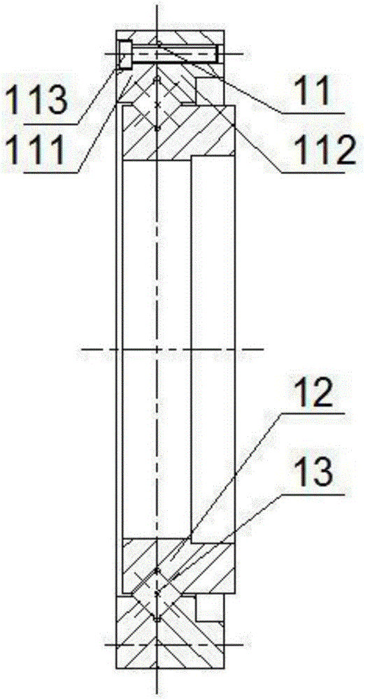
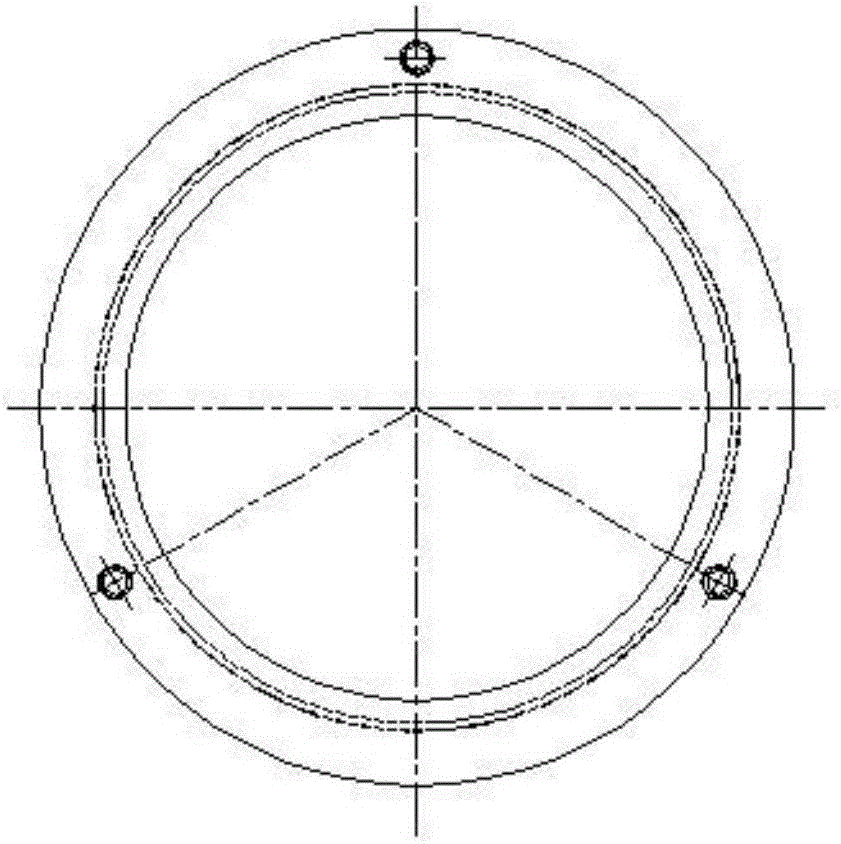
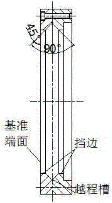
[0094] Embodiment 1, as figure 1 Shown is a schematic diagram of a crossed roller bearing, which is a crossed cylindrical roller bearing with a convex outer ring, including an outer ring 11 with a ring-shaped inner V-shaped raceway, an inner ring 12 with a ring-shaped outer V-shaped raceway, embedded Cylindrical rollers 13 arranged crosswise between the V-shaped raceway of the outer ring and the V-shaped raceway of the inner ring. The outer ring 11 is designed as a two-half structure, including two halves of rings 111 and 112. The two halves of the rings are connected by several connecting screws. 113 connections are fastened to an integral outer ring. From Figure 2B and image 3 It can be seen that the angle between the V-shaped raceways of the inner ring and the outer ring near the respective reference end faces and the respective reference end faces is 45 degrees, and the angle between the raceways on both sides is 90 degrees. The raceway is sandwiched between the ring...

Embodiment 2

[0098] Example 2. Partially split inner ring with convex cross tapered roller bearing - logarithmic curve convex

[0099] Partially split inner ring with convex crossed tapered roller bearings such as Figure 4 As shown, it includes the outer ring 21, the inner ring 22, the tapered rollers 23 embedded between the V-shaped raceway of the outer ring and the V-shaped raceway of the inner ring and arranged crosswise, the cone top of one row of tapered rollers and the other row of cones The cone tops of the rollers fall on two points on both sides of the bearing on the center line of rotation of the bearing respectively. Outer ring 21 such as Figure 5 As shown, it is an overall structure, and the inner ring 22 is as Figure 4 , Figure 6A , 6B As shown in and 6C, in order to fill a sufficient number of tapered rollers 23 into the bearing, the inner ring 22 is designed as a partially split structure with a raceway block, and the inner ring 22 is composed of a notched inner ring...

Embodiment 3

[0101] Embodiment 3. Structure, processing and assembly of partially split inner ring with convex cross tapered roller bearing

[0102] For partially split crossed roller bearings, only one of the rings, the inner ring or the outer ring, needs to be partially split, Figure 4 The assembly drawing of the cross-tapered roller bearing with convex inner ring is given, Figure 5 is a cross-sectional view of the outer ring 21, it can be seen that the outer ring 21 is an integral structure, Figure 6A is a sectional view of the inner ring 22, Figure 6B is the left side view of the inner circle 22, Figure 6C yes Figure 6B In the A-direction view, it can be seen that the inner ring 22 is a partially dissected structure, which is composed of a notched inner ring 221, a raceway block 222 and a connecting screw 223, wherein the connecting screw 223 fixes the block 222 on the notched On the inner ring 221, the blockage matches the gap. The manufacturing method of the partially spli...


PUM

PropertyMeasurementUnit
surface roughnessaaaaaaaaaa

Abstract

The invention provides a crossed roller bearing with a roller path with convexity and a manufacturing method thereof. The crossed roller bearing with the roller path with convexity is characterized in that the V-shaped roller path of the crossed roller bearing has the convexity; a convex shape comprises a straight line, an arc-shaped quadratic curve and a logarithmic curve; and the V-shaped roller path with the convexity is formed in a crush grinding mode or a precision hard turning mode, or the V-shaped roller path with the convexity and other important finish machining surfaces of a loop are sequentially formed in a precision hard turning mode during one-time clamping positioning. According to the crossed roller bearing, machined according to the design, with the roller path with the convexity, compared with a grinding-formed crossed roller bearing with a roller path without convexity, the fringe effect of a roller-roller path contact pair is greatly reduced or completely avoided, the contact state between the outer circle face and the end face of a roller, and the roller path is improved, the bearing operating friction power consumption is reduced, the temperature rise is decreased, and the deflection-resisting capability of the bearing is improved; and accordingly, the operating precision, the bearing capability and the operating reliability of the bearing are improved, the service life of the bearing is prolonged, and very important practical engineering significance is achieved.

Description

technical field [0001] The invention relates to the technical field of rolling bearings, in particular to a crossed roller bearing with a convex raceway and a manufacturing method thereof. Background technique [0002] In 2014100202253 Rolling Bearing Formed by Precision Hard Turning of Ferrules and Its Processing Method, the applicant once described the structure of the raceway of ordinary structure bearings and the hard turning processing method of the raceway, which solved the problem of the raceway in the grinding and forming process of the raceway. Restricted cross-sectional shape design, grinding deterioration or even burns, etc., so that the surface of the ferrule can be designed for the working conditions, and can be formed with very high shape and position accuracy, which is suitable for the design of high-performance rolling bearings such as high sealing and high reliability. And manufacturing has engineering practical significance. However, the existing technolog...

Claims


Application Information

Patent Timeline
Patent Type & Authority Applications(China)
IPC IPC(8): F16C33/58F16C33/64F16C19/54B23P15/00
CPCB23P15/003F16C19/54F16C33/583F16C33/64
Inventor 赵联春赵思澄陈淑英
Owner SHANGHAI F&S BEARING TECH
Why Eureka
Try Eureka