Micro-valve system based on flow path state

A technology of micro-valve and flow path, which is applied in the direction of valve devices, mechanical equipment, engine components, etc., can solve the problems of complex processing and easy leakage, and achieve the effects of simple control method, comprehensive sample injection control, and easy production and processing

Active Publication Date: 2016-12-07
TARGETINGONE CORP
View PDF5 Cites 3 Cited by
  • Summary
  • Abstract
  • Description
  • Claims
  • Application Information

AI Technical Summary

Problems solved by technology

But there are also deficiencies such as easy leakage and complicated processing.

Method used


Image

  • Micro-valve system based on flow path state
  • Micro-valve system based on flow path state
  • Micro-valve system based on flow path state

Examples


Embodiment 1

[0026] The working mode of embodiment 1 channel valve

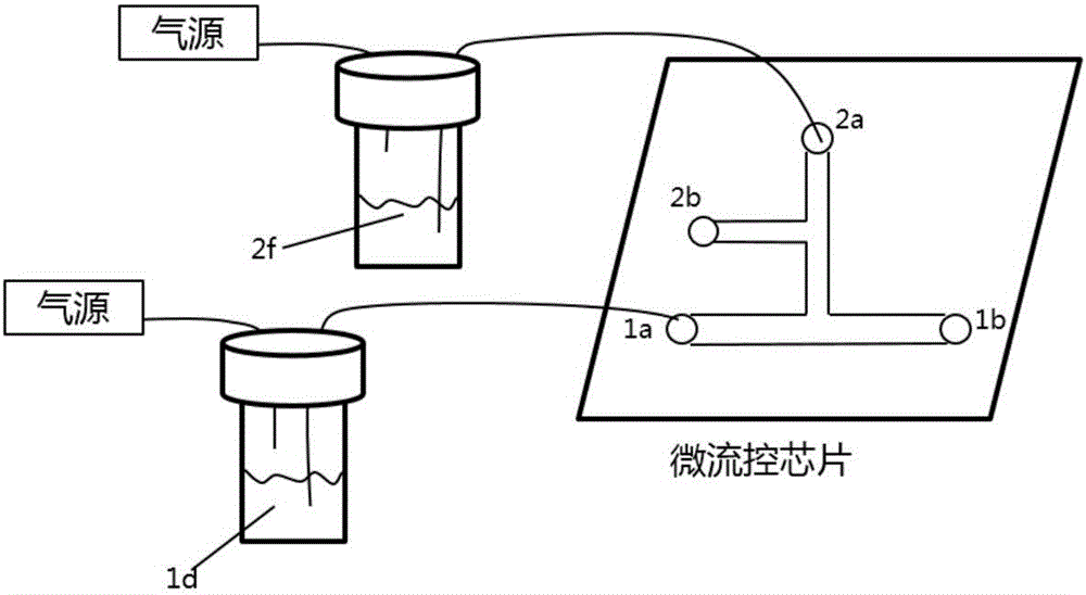
[0027] figure 1 Shown is a schematic diagram of the pneumatic sampling system outside the microfluidic chip. Among them, the air source is an air compressor with variable pressure, which can generate a relative pressure of 0-0.7MPa, which is used as the injection power of the liquid sample. The gas source is connected to the sample injector through a conduit. The injection sample 2f and the main flow sample 1d are respectively installed in the two injectors. The sample flows through a tube inserted into the bottom of the injector to the inlet of the microfluidic chip and eventually into the microtubes. By changing the sampling pressure of each gas source, each flow path valve can be in the desired working mode.

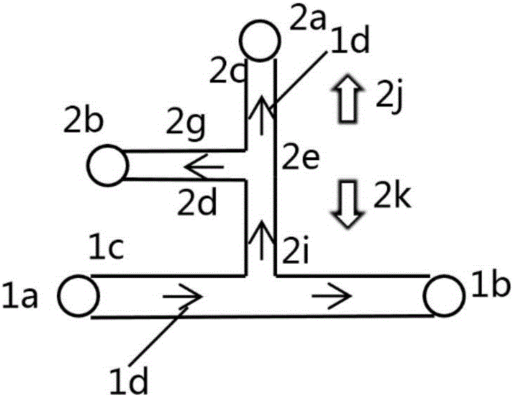
[0028] figure 2 Shown is a schematic diagram of the principle of the microvalve system in reverse injection mode. Wherein, the main channel 1 includes a main channel inlet 1a, a main channel outlet 1b, and...

Embodiment 2

[0032] Example 2 Using a multi-sample injection structure composed of multi-stream valves to realize multi-site DNA detection

[0033] Image 6 Shown is a schematic structural diagram of a multi-sample injection chip composed of multiple flow path valves. The chip structure includes a main channel 1 and multiple sample injection channels. The situation shown in the figure is that the sample injection flow path 3 is in the working state of forward sample injection, and the other sample flow paths are in the working mode with the valves closed. Therefore, at the main channel outlet 1b, a mixed sample containing the main channel sample 1d and the injection sample 3f will be obtained, and the concentration of the injection sample 3f in the mixed sample is determined by the pressure at the injection inlet 3a. In the same way, different sample combinations can be obtained at the outlet 1b by changing the working mode of other sample injection flow paths.

[0034] for further clar...


PUM


Abstract

The invention discloses a micro-valve system based on the flow path state. The micro-valve system comprises a microfluidic chip and a pressure sample inlet system. The chip comprises a main flow path and multiple sample inlet flow paths. Switching among three work modes including a reverse sample inlet mode, a valve closing mode and a forward sample inlet mode of the microfluidic chip is achieved by adjusting the magnitude of a pressure source of a sample inlet device and a pressure source of a main flow path sample. The micro-valve system is simple in structure, machining and integrating are easy, a control method is simple, control equipment is low in complexity, and the opening degree of the micro-valve system is controllable.

Description

technical field [0001] The invention relates to the field of microfluidic chips, in particular to a microvalve system based on flow path state. Background technique [0002] Microfluidics is a new type of tool that integrates the basic operation units such as sample preparation, reaction, separation, and detection in the process of biological, chemical, and medical analysis into a micron-scale chip, and automatically completes the entire analysis process. . Microfluidic chips process functional units such as micropipes, microvalves, micropumps, microreactors, electrodes, etc. Various operations on samples at the micron scale. Among them, the microvalve is mainly responsible for supervising the work of each flow path in the chip, regulating the pressure and movement state of the fluid in the chip, similar to the "traffic lights" in the urban traffic system, and is an important unit in the microfluidic chip. There are mainly three types of common microvalves. [0003] (1) ...

Claims


Application Information

Patent Timeline
Patent Type & Authority Applications(China)
IPC IPC(8): F16K99/00
CPCF16K99/0001F16K2099/0073F16K2099/0082
Inventor 苏世圣郭永荆高山王博张妙琪柳哲高华方祝令香杨文军王勇斗
Owner TARGETINGONE CORP
Why Eureka
Try Eureka