
Advanced detection system and method of forward array radar mounted on cutter of TBM (tunnel boring machine)

A technology of advanced detection and array radar, which is applied in radio wave measurement systems, measurement devices, radio wave reflection/reradiation, etc., can solve the problems of complex installation of test equipment, long test time, and inability to obtain 3D information of TBM geological bodies

Active Publication Date: 2016-12-07
SHANDONG UNIV
View PDF6 Cites 7 Cited by
  • Summary
  • Abstract
  • Description
  • Claims
  • Application Information

AI Technical Summary

Problems solved by technology

BEAM is a one-dimensional focused induced polarization method. Its disadvantages are that the installation of test equipment is complicated and the test time is long, which seriously affects the construction progress; However, the detection distance is small, and tomography detection is not used, so the three-dimensional information of the geological body in front of the TBM working face cannot be obtained, and the water volume cannot be predicted.
In addition, judging from the application of the BEAM method in several tunnels in my country, the forecast results are not ideal and have not been popularized, and need to be improved and perfected
[0005] To sum up, it can be seen that there is no very effective and practical advanced geological prediction technology and device for TBM construction tunnels at present.

Method used


Image

  • Advanced detection system and method of forward array radar mounted on cutter of TBM (tunnel boring machine)
  • Advanced detection system and method of forward array radar mounted on cutter of TBM (tunnel boring machine)
  • Advanced detection system and method of forward array radar mounted on cutter of TBM (tunnel boring machine)

Examples


Embodiment Construction

[0053] The present invention will be further elaborated below through specific examples and accompanying drawings. It should be pointed out that what is disclosed below is only a preferred embodiment of the present invention, and certainly cannot limit the scope of rights of the present invention with this. Under the premise of departing from the principle of the present invention, those skilled in the art can also make some improvements and modifications, and these improvements and modifications should also be regarded as the protection scope of the present invention.

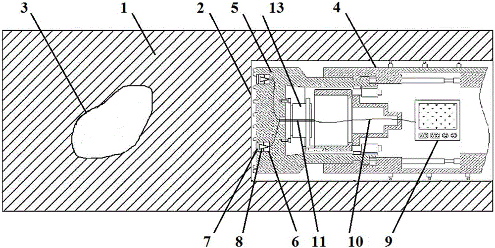
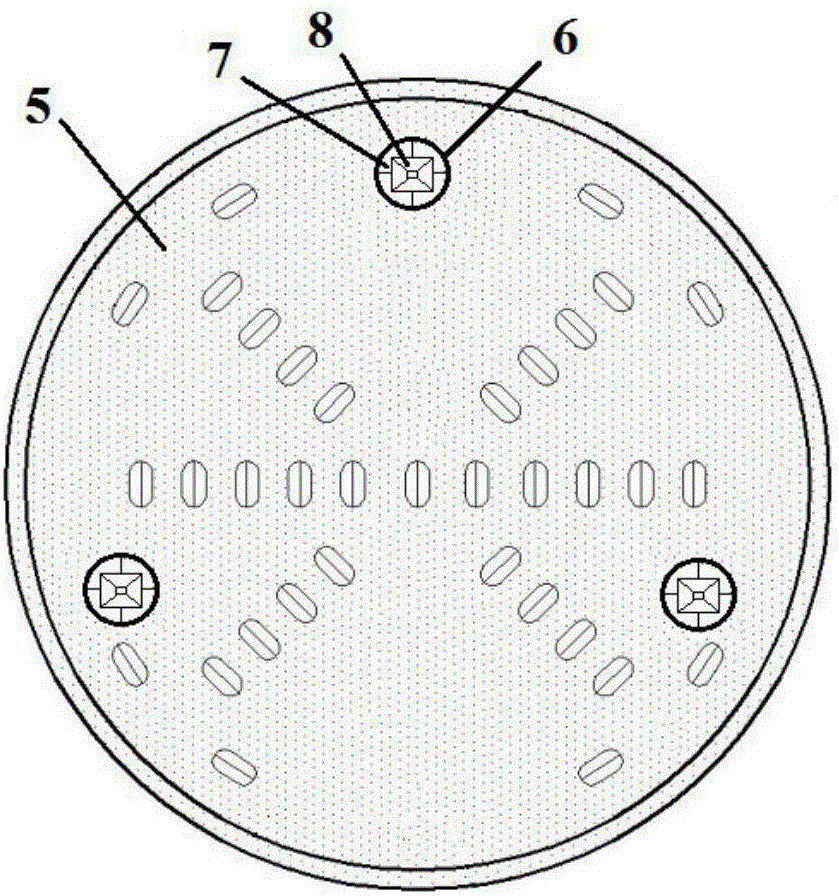
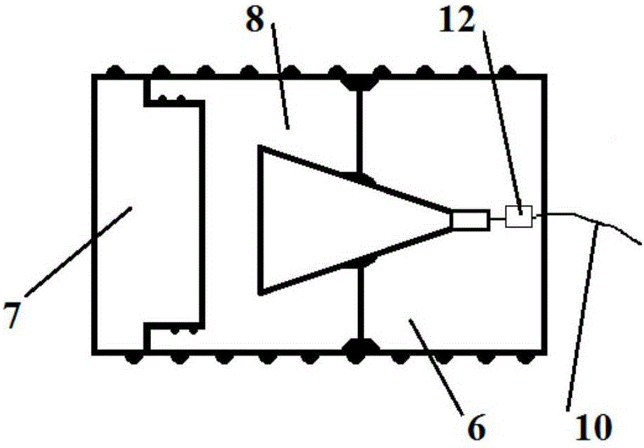
[0054] A forward array radar advanced detection device system mounted on a TBM cutter head includes three modules: a detection module, a processing module and a data transmission module. The detection module includes: three slots reserved on the outer circumference of the TBM cutterhead 5; a metal protection box 6 with a front opening in the reserved slot of the cutterhead; placed in the metal protection box 6 ...


PUM


Abstract

The invention provides an advanced detection system and method of a forward array radar mounted on the cutter of a TBM (tunnel boring machine). According to the advanced detection system and method of the invention, three automatic-transmitting and automatic-receiving ground penetrating radar antennas are arranged on the cutter of the TBM so as to form an array radar and carry out rotation circulatory detection respectively along a circumferential direction; metal protection boxes are arranged at the lateral sides and rear sides of the radar antennas so as to protect the antennas and shield influences on radar signals caused by machines and cables located behind; non-metal material protection plates are arranged at front of the radar antennas so as to protect the radar antennas, and therefore, the integrity of the cutter can be protected, and radar detection signals are not affected; a radar main unit is connected with the radar antennas through optical fibers, and therefore, influences on data transmission caused by the machines and cables of the TBM can be eliminated; and a photoelectric converter is adopted to convert optoelectronic signals. Since three kinds of radar antennas with different main frequencies are adopted, detection distance and resolution can be both considered; and the radar main unit integrates a function for processing and imaging obtained signals, and therefore, computation speed is high, real-time detection and real-time imaging can be achieved basically.

Description

technical field [0001] The invention relates to the field of advanced geological prediction of unfavorable geology of TBM construction tunnels, in particular to a forward array radar advanced detection system and method mounted on a TBM cutter head. Background technique [0002] Now my country's tunnel construction is in full swing, and the proportion of full-face tunnel boring machine (Tunnel Boring Machine, TBM for short) construction is getting higher and higher. TBM is a new type of advanced tunnel construction machine that uses rotary cutters to excavate and simultaneously breaks the surrounding rock in the tunnel to form the entire tunnel section. Compared with the traditional drilling and blasting construction method, the TBM construction method has many advantages such as "fast construction speed, small excavation disturbance, safety and environmental protection". However, TBM machinery has poor adaptability to changes in geological conditions. When faults, broken z...

Claims


Application Information

Patent Timeline
Patent Type & Authority Applications(China)
IPC IPC(8): G01S13/88
CPCG01S13/885
Inventor 刘斌张凤凯聂利超李术才李尧宋杰刘征宇
Owner SHANDONG UNIV
Learn More