Supercharge Your Innovation With Domain-Expert AI Agents!

A clamping tool for heating and a solid solution heat treatment device

A technology of solid solution heat treatment and clamping tooling, which is applied in heat treatment furnaces, heat treatment equipment, manufacturing tools, etc., can solve the problems of inability to realize partial solid solution heat treatment, not fully utilizing its own characteristics, and no clamping tooling, etc., to improve equipment The effect of safety, fast speed and convenient heating tooling

Active Publication Date: 2019-04-12
HIMILE MECHANICAL MFG
View PDF6 Cites 0 Cited by
  • Summary
  • Abstract
  • Description
  • Claims
  • Application Information

AI Technical Summary

Problems solved by technology

[0002] At present, the solution heat treatment methods mainly include heating in the furnace (resistance type, gas type) and heating in the horizontal intermediate frequency induction furnace. The common solution heat treatment method is suitable for large-scale and large-scale workpiece production, but for Odd-shaped products such as bent tubes, super-long, super-wide or super-high workpieces are difficult to put into the heating tooling (or furnace) for heat treatment due to problems such as hoisting and space constraints, especially when performing local solid solution heat treatment due to the need to Due to the limited space of the heat treatment part and the interference of heating elements and other factors, it is basically impossible to achieve local solid solution heat treatment
Since this kind of heat treatment method requires its own preheating, the cost is extremely high when processing such workpieces in small batches, and the acceleration speed is slow, and the own characteristics of such workpieces are not fully utilized. In addition, the heating for such products , and there is no suitable clamping tooling

Method used


Image

  • A clamping tool for heating and a solid solution heat treatment device
  • A clamping tool for heating and a solid solution heat treatment device

Examples


Embodiment 1

[0031] A clamping tool for heating, including a conductive part with an electrode wire connection block, the conductive part is provided with a clamping part for clamping a workpiece, the shape of the clamping part is adapted to the shape of the workpiece, and the middle part of the conductive part Bending is set to clamp the workpiece from both sides of the workpiece, and fasteners are provided on the conductive part to make the conductive part and the workpiece fit closely; the above-mentioned clamping tool is more convenient for the needs The solution heat treated workpiece is clamped to facilitate subsequent solution heat treatment.

Embodiment 2

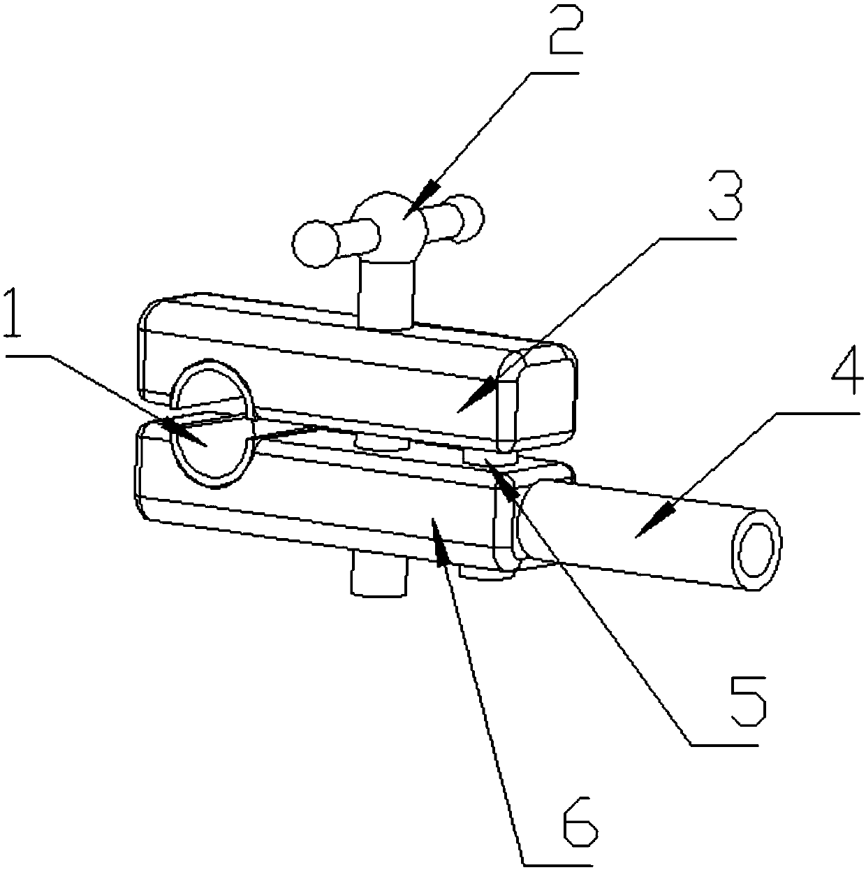
[0033] Such as figure 2 As shown, a clamping tool for heating includes a conductive part with an electrode wire connection block 4, the conductive part clamps the workpiece, and the conductive part includes a first conductive clamping part 3 and a second conductive clamping part 6, Fasteners are arranged between these two conductive clamps so that the conductive parts and the workpiece 10 are closely attached, and a conductive block 5 is arranged between the two conductive clamps; The workpiece 10 is respectively clamped on the two sides, and fastened by the fastener 2, and the first conductive clamp 3 and the second conductive clamp 6 are connected by the conductive block 5 to ensure smooth conduction.

[0034] Wherein, the lower surface of the first conductive clamping part 3 is provided with a first groove, and the upper surface of the second conductive clamping part 6 is provided with a second groove 1, through which the first groove and the second groove are matched from...

Embodiment 3

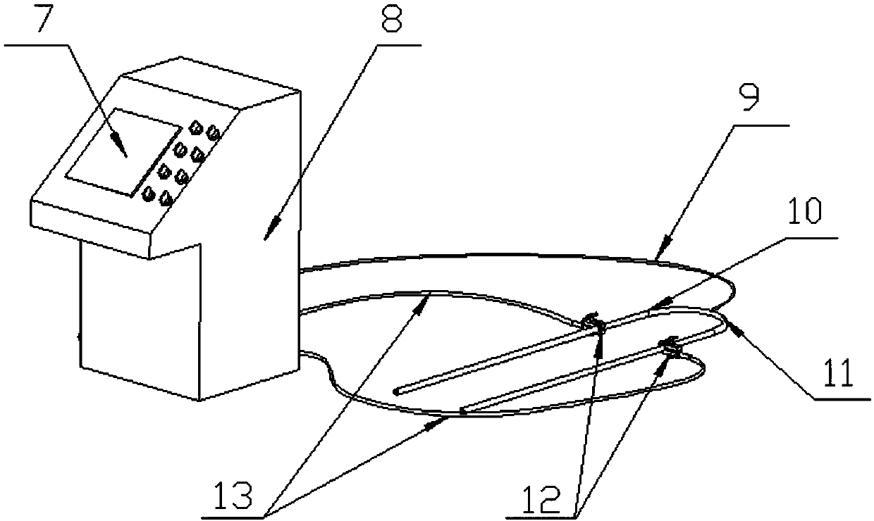
[0038] Such as figure 1 As shown, the solution heat treatment solution includes: a temperature acquisition component, a control system, a power output component, an alarm mechanism and a clamping tool 12 .

[0039] The temperature acquisition part adopts S-type high-temperature thermocouple 9 for workpiece temperature signal acquisition. One or more temperature acquisition parts can be set to avoid false alarms caused by a certain thermocouple failure. At the same time, it is convenient to compare and observe the work of thermocouple 9 situation; in order to facilitate the temperature monitoring of the heated area 11 of the workpiece, the thermocouple 9 is connected to the control system; the thermocouple 9 is connected to the control system through a temperature transmitter, and a high-stability temperature transmitter is used to convert the external temperature signal It is 4-20ma signal input to the control system. The thermocouple 9 plays the role of isolating the externa...


PUM


Abstract

The invention discloses a clamping tool used for heating and a solid solution thermal treatment device. The clamping tool comprises a conductive part; the conductive part coats part of a workpiece; the conductive part comprises a first conductive clamping part and a second conductive clamping part; a fastening part is arranged between the two conductive clamping parts for enabling the conductive part to be in contact with the workpiece; and a conductive block is arranged between the two conductive clamping parts. The solid solution thermal treatment device disclosed by the invention adopts a direct heating mode, is high in speed, is high in efficiency, and does not need to use a heating plate and other heat conduction modes, so that heat conduction efficiency is high, thermal treatment efficiency is improved by 30 times or more, and cost is reduced by 200%. The solid solution thermal treatment device disclosed by the invention is not limited by furnace space, is high in flexibility, and can be used by only needing to carry out effective thermal insulation treatment; and a power output shaft realizes synchronization of chopping voltage regulation and current limitation, control and implementation parts form full-closed loop control, and height is reliable and stable.

Description

technical field [0001] The invention relates to solid solution heat treatment, in particular to a clamping tool for heating and a solid solution heat treatment device. Background technique [0002] At present, the solution heat treatment methods mainly include heating in the furnace (resistance type, gas type) and heating in the horizontal intermediate frequency induction furnace. The common solution heat treatment method is suitable for large-scale and large-scale workpiece production, but for Odd-shaped products such as bent tubes, super-long, super-wide or super-high workpieces are difficult to put into the heating tooling (or furnace) for heat treatment due to problems such as hoisting and space constraints, especially when performing local solid solution heat treatment due to the need to Due to the limited space of the heat treatment part and the interference of heating elements and other factors, it is basically impossible to achieve local solid solution heat treatment...

Claims


Application Information

Patent Timeline
Patent Type & Authority Patents(China)
IPC IPC(8): C21D9/00B25B9/02
CPCB25B9/02C21D9/00
Inventor 赵宏军辛峰孙礼传魏猛
Owner HIMILE MECHANICAL MFG
Features
  • R&D
  • Intellectual Property
  • Life Sciences
  • Materials
  • Tech Scout
  • Unparalleled Data Quality
  • Higher Quality Content
  • 60% Fewer Hallucinations
Learn More