Opening-free heat insulation cage ingot casting device and method

A heat insulation cage and ingot casting technology, which is applied in the field of polysilicon ingot casting, can solve the problems of ineffective control of process power consumption, inability to improve quality, and heat loss, etc., and achieve the reduction of the scrapping ratio of hidden cracks and the photoelectric conversion efficiency. Improve and reduce the impact of thermal field

Inactive Publication Date: 2016-12-14
YICHANG CSG POLYSILICON CO LTD
View PDF10 Cites 5 Cited by
  • Summary
  • Abstract
  • Description
  • Claims
  • Application Information

AI Technical Summary

Problems solved by technology

[0007] 1. In the GT furnace type described above, the semi-melting process retains a certain height of the seed crystal in the later stage of melting. After opening the heat insulation cage, due to a large amount of heat loss from the surrounding of the heat insulation cage, in order to avoid the surrounding silicon liquid part in advance Crystallization, GT furnace type, uses the heat of the side heater to compensate for the lost heat, causing the surrounding seed crystals to absorb the excess heat emitted by the side heaters and melt, which cannot effectively grow high-efficiency polycrystalline silicon ingots using the seed crystal as the seeding carrier , thereby affecting the photoelectric conversion efficiency of the silicon wafer, and the quality cannot be improved;
[0008] 2. In the GT furnace type described above, since a large amount of heat is dissipated from around the heat insulation cage after opening the heat insulation cage, the isothermal gradient in the thermal field is not horizontal, so that the crystallization direction of the silicon ingot cannot be completely vertically upward, and then The number of dislocations in the growth of the silicon ingot cannot be effectively controlled, so that the photoelectric conversion efficiency of subsequent silicon wafer products is low, and the stability is poor, and the quality cannot be improved;
[0009] 3. In the GT furnace type described above, since a large amount of heat is dissipated from around the heat insulation cage after opening the heat insulation cage, the temperature difference between the top and the bottom of the thermal field continues to increase, and a large internal thermal stress is formed in the silicon ingot , when the silicon ingots produced encounter external forces (such as sticking pots, collisions, square cutting, etc.), the proportion of adverse phenomena such as chipping, hidden cracks, and peeling increases, resulting in a decrease in yield and an increase in cost ;
[0010] 4. In the GT furnace type and ALD furnace type described above, since the heat insulation cage or heat insulation board is opened during the silicon ingot growth process, a large amount of heat is lost. In order to ensure that the growth temperature does not affect the silicon The quality of the ingot requires more power from the heater to compensate for this part of the temperature loss, so the power consumption of the entire process cannot be effectively controlled, the energy consumption of the ingot is high, and the cost rises
[0011] The above problems are mainly due to the fact that in the ingot casting process, the heat insulation cage must be opened for heat dissipation in the later stage of melting and the entire crystal growth process, and the heat insulation cage must be opened in the stable thermal field itself, which will affect the temperature gradient, energy consumption ratio, and thermal stress in the thermal field. Both caused a large impact. At present, the ingot casting equipment does not have a good control method for this impact.

Method used


Image

  • Opening-free heat insulation cage ingot casting device and method
  • Opening-free heat insulation cage ingot casting device and method
  • Opening-free heat insulation cage ingot casting device and method

Examples


Embodiment 1

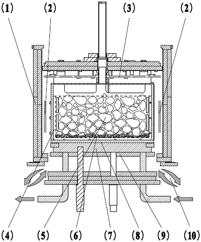
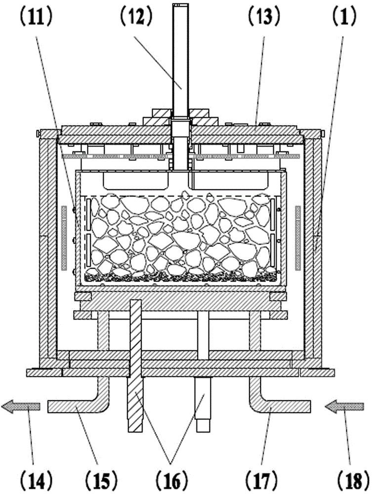
[0045] An ingot casting device without opening a heat insulation cage, comprising a heat insulation cage 1, a side heater 2 is provided on the inner surface of the heat insulation cage 1, a top heater 3 is provided on the inner top of the heat insulation cage 1, and the The side heater 2 and the top heater 3 are separately controlled by dual power supplies;

[0046] The interior of the heat insulation cage 1 is provided with a cavity for placing the crucible 4 formed by a graphite base plate 8 and the crucible graphite guard plates 11 on both sides thereof, and the cavity is supported by a graphite support column 16 through the bottom of the heat insulation cage 1;

[0047] The bottom of the graphite base plate 8 is provided with an air-cooled DS block 7 and a bottom insulation board 9, and the inside of the air-cooled DS block 7 is provided with circulating cooling argon;

[0048] The top insulation plate 13 is provided with an argon gas channel and a graphite observation hol...

Embodiment 2

[0062] An ingot casting device without opening a heat insulation cage, comprising a heat insulation cage 1, a side heater 2 is provided on the inner surface of the heat insulation cage 1, a top heater 3 is provided on the inner top of the heat insulation cage 1, and the The side heater 2 and the top heater 3 are separately controlled by dual power supplies;

[0063] The interior of the heat insulation cage 1 is provided with a cavity for placing the crucible 4 formed by a graphite base plate 8 and the crucible graphite guard plates 11 on both sides thereof, and the cavity is supported by a graphite support column 16 through the bottom of the heat insulation cage 1;

[0064] The bottom of the graphite base plate 8 is provided with an air-cooled DS block 7 and a bottom insulation board 9, and the inside of the air-cooled DS block 7 is provided with circulating cooling argon;

[0065] The top insulation plate 13 is provided with an argon gas channel and a graphite observation hol...

Embodiment 3

[0078] An ingot casting device without opening a heat insulation cage, comprising a heat insulation cage 1, a side heater 2 is provided on the inner surface of the heat insulation cage 1, a top heater 3 is provided on the inner top of the heat insulation cage 1, and the The side heater 2 and the top heater 3 are separately controlled by dual power supplies;

[0079] The interior of the heat insulation cage 1 is provided with a cavity for placing the crucible 4 formed by a graphite base plate 8 and the crucible graphite guard plates 11 on both sides thereof, and the cavity is supported by a graphite support column 16 through the bottom of the heat insulation cage 1;

[0080] The bottom of the graphite base plate 8 is provided with an air-cooled DS block 7 and a bottom insulation board 9, and the inside of the air-cooled DS block 7 is provided with circulating cooling argon;

[0081] The top insulation plate 13 is provided with an argon gas channel and a graphite observation hol...


PUM


Abstract

The invention relates to field of polycrystalline silicon ingot casting, in particular to an opening-free heat insulation cage ingot casting device and method. The device comprises a heat insulation cage, wherein a lateral heater is arranged on the inner side face of the heat insulation cage, a top heater is arranged at the top in the heat insulation cage, and the lateral heater and the top heater are separately controlled by double power supplies. In a melting step, the temperature of an air cooling DS block is controlled not to be higher than 1400 DEG C. In astep of change from melting to crystal growth, the temperature of an air cooling DS block is 1300-1360 DEG C, the temperature of the top heater is 1530-1545 DEG C. In a crystal growth step, the temperature of the top heater is reduced from 1430 DEG C to 1400 DEG C, and the temperature of the air cooling DS block is reduced from 1300 DEG C to 1000 DEG C. By the adoption of the opening-free heat insulation cage ingot casting device, the heat insulation cage cannot be needed to be opened, the subfissurescrap ratio of cut silicon wafers is reduced by about 15%, the dislocation number of silicon ingots in growth is effectively controlled, the photoelectric conversion efficiency of silicon wafer products is high, and the stability is good.

Description

technical field [0001] The invention relates to the field of polycrystalline silicon ingot casting, in particular to an ingot casting device and method without opening a heat insulation cage. Background technique [0002] At present, in the field of polycrystalline ingot casting in the photovoltaic industry, in order to obtain silicon wafers with high photoelectric conversion efficiency, the semi-melting process of laying seed crystals (small silicon material) on the bottom of the crucible and nucleating and growing on the seed crystals is the mainstream process. In the traditional polycrystalline ingot semi-melting process, in order to ensure the retention of the seed crystal in the melting process step and the necessary subcooling degree required to maintain the growth in the growth process step, it is determined by the opening degree of the heat insulation cage Adjustment, control the bottom temperature required by the entire ingot semi-melting process by changing the ope...

Claims


Application Information

Patent Timeline
Patent Type & Authority Applications(China)
IPC IPC(8): C30B28/06C30B29/06
CPCC30B28/06C30B29/06
Inventor 周晓康李春林李旭敏李普鞠磊肖宗卫李宏
Owner YICHANG CSG POLYSILICON CO LTD
Why Eureka
Try Eureka