In-hole seismic probe, surrounding rock detection device and detection method

A technology of detection device and detection method, applied in measurement device, seismology, geophysical measurement and other directions, can solve the problems of difficult practical operation, heavy workload, long time required, etc., to achieve easy portability and installation, and isolation of sound wave interference. , The real and reliable effect of the data

Inactive Publication Date: 2016-12-14
ANHUI HUIZHOU GEOLOGY SECURITY INST
View PDF4 Cites 15 Cited by
  • Summary
  • Abstract
  • Description
  • Claims
  • Application Information

AI Technical Summary

Problems solved by technology

Water is used as the coupling medium between the acoustic wave probe and the rock hole wall, which has high requirements on water flow, pressure and water quality, and is difficult to operate in practice, and it is difficult to test in soft rock and coal seams; For one-time consumption, the cost is high, the accuracy is poor, and the time required is long; the geological radar method is susceptible to metal interference; the resistivity method is convenient for measurement, the test range is large, and the technical requirements for good electrode layout are high; the permeability method The disadvantage is that for soft rock and water-swelling rock formations, it is difficult to test and the workload is large; most of the seismic wave method is detected outside the borehole, and the detection range is large, but for in-hole detection, probe layout and instrument installation are more difficult, domestic application Also less (Jia Yingxuan, Song Hongwei, Testing Technology and Discussion of Loose Circle of Surrounding Rock of Roadway, 2004(10): 149-150)

Method used


Image

  • In-hole seismic probe, surrounding rock detection device and detection method
  • In-hole seismic probe, surrounding rock detection device and detection method
  • In-hole seismic probe, surrounding rock detection device and detection method

Examples


Embodiment Construction

[0029] In order to make the object, technical solution and advantages of the present invention clearer, the present invention will be further described in detail below in conjunction with the accompanying drawings and embodiments. It should be understood that the specific embodiments described here are only used to explain the present invention, not to limit the present invention.

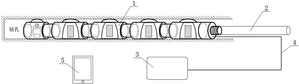
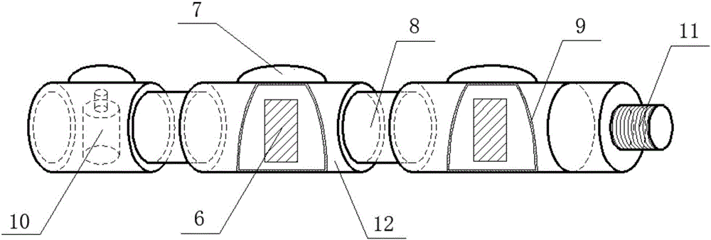
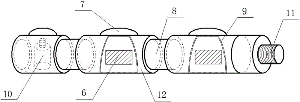
[0030] see figure 1 According to the present invention, the surrounding rock loosening and surrounding rock classification detection device based on the seismic wave method includes a seismic probe 1 in a hole, a guide rod 2, a connecting line 4 and processing equipment. The in-hole seismic probe 1 is pushed into the borehole through the guide rod 2 and is electrically connected with the processing equipment through the connection line 4 . The processing device obtains and processes seismic signals in the surrounding rock target detection area through the in-hole seismic probe 1 .

[0031] The pr...


PUM


Abstract

The invention discloses an in-hole seismic probe, a surrounding rock detection device and a detection method. The in-hole seismic probe comprises a seismic source device and at least two signal receiving devices connected in sequence, wherein the seismic source device is located at the front end of the in-hole seismic probe; each signal receiving device comprises a carrier, at least one sensor core, at least one pinning coupling device, a seismic isolation device and at least one sound insulation device; all carriers of the signal receiving devices are lined up; the outer wall of each carrier is provided with at least one pinning coupling device; the adjacent two carriers are connected via the seismic isolation device; each carrier is internally provided with at least one sensor core; and the sensor cores in each carrier are covered with at least one sound insulation device. The in-hole seismic probe of the invention has the beneficial effect that portability is realized; multi-angle drilling self coupling is realized; the seismic wave data have a high signal-to-noise ratio; and a seismic exploration technique can be used for forming a wave velocity result, a frequency curve, a surface wave testing result, reflection and scattering profiles and the like.

Description

technical field [0001] The present invention relates to a seismic probe in a hole, a detection device using the seismic probe in a hole, and a detection method for the detection device, in particular to a seismic probe in a hole, and a seismic wave method based on the seismic wave method in a hole using the seismic probe in a hole. Surrounding rock looseness and surrounding rock classification detection device, detection method of the detection device. Background technique [0002] The crustal rock formation in the natural state is usually in a state of stress balance. Due to the excavation of roadways in the rock mass, the boundary conditions of the rock mass have been changed, the relative balance of the rock mass has been destroyed, and the natural stress field in the rock mass has changed. A new stress balance is regenerated within a certain range around the roadway. The so-called surrounding rock loosening zone is due to the redistribution of surrounding rock stress, f...

Claims


Application Information

Patent Timeline
Patent Type & Authority Applications(China)
IPC IPC(8): G01V1/20G01V1/22
CPCG01V1/20G01V1/223G01V2210/142G01V2210/16
Inventor 刘惠洲周官群唐润秋任川舒玉峰王宗涛邓涛闫伟吴记军
Owner ANHUI HUIZHOU GEOLOGY SECURITY INST
Why Eureka
Try Eureka