
Integrated air-supply unit
A technology of air supply and air spring, applied in the direction of vehicle subunit functions, pump components, components of pumping devices for elastic fluids, etc., can solve the problems of not being able to manufacture cost-effectively, troublesome connections, etc., and achieve improved diagnostic performance and fault protection performance, good turn-on time, small torque fluctuation effect
Patent Information
- Authority / Receiving Office
- CN · China
- Patent Type
- Applications(China)
- Current Assignee / Owner
- Publication Date
- 2016-12-14
Smart Images
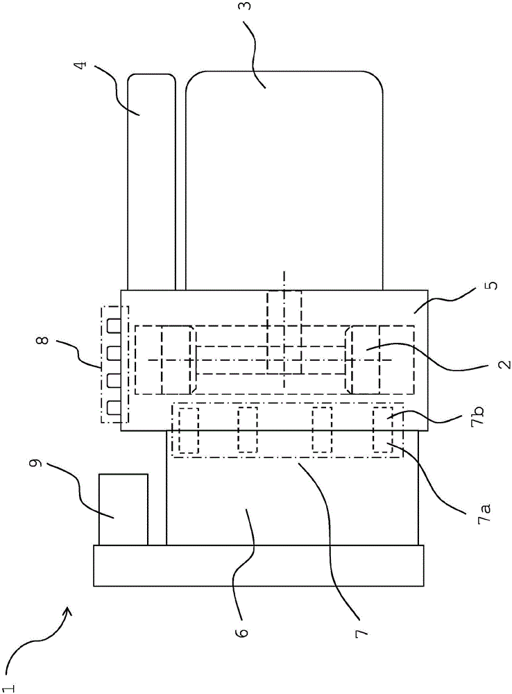
Figure 1 
Figure 2 
Figure 3
Abstract
Description
technical field
[0001] The invention relates to an integrated air supply unit, especially for an air spring system of a motor vehicle, said integrated air supply unit comprising an air compressor with a motor and an air dryer, wherein the air compressor is connected with the motor, the air The dryer and the pneumatic connections together form a functional unit. Background technique
[0002] An air spring arrangement for a vehicle is known from document DE 10 2005 030 726 A1, which comprises the necessary components of current air spring systems. The air spring device has a compressor, an air dryer, a pressure accumulator, as well as various valves and compressed air lines. In addition, the gas spring system has a pressure sensor and is controlled by a controller.
[0003] The main components of an air supply device for an air spring system according to the prior art include an air compressor, valves and a controller, which are usually installed in the vehicle in a manner d...
Examples
Embodiment Construction
[0037] figure 1 An integrated air supply unit 1 for an air spring system of a motor vehicle is shown in a schematic diagram. Inside the pneumatic block 5 is shown an air compressor 2 driven by an electric motor 3 mounted at the front. In addition, an air dryer 4 is installed at the front.
[0038] The pneumatic block 5 has receptacles, not shown in detail, for individual components. A plurality of pneumatic valves 7 are schematically shown, which are arranged inside the pneumatic block 5 and are arranged adaptively to one another in the electronic controller 6 .
[0039] Integrated in the pneumatic block 5 is a drive unit 7 a of a pneumatic valve 7 comprising a valve core, a bush, an armature, a spring and a sealing seat. The solenoid valve coil 7 b of the pneumatic valve 7 is integrated in the electronic control unit 6 . The drive unit 7a and the solenoid valve coil 7b are fittingly connected to each other.
[0040] The pneumatic block 5 also includes channels, not shown, ...