Spark plasma sintering system

A discharge plasma and sintering furnace technology, applied in the field of ion sintering system, can solve the problems of large side temperature measurement barrier, unsatisfactory product quality, poor temperature control effect, etc., achieve high measurement and control accuracy, increase contact area, good molding effect

Active Publication Date: 2016-12-21
浙江晨华科技有限公司
View PDF7 Cites 14 Cited by
  • Summary
  • Abstract
  • Description
  • Claims
  • Application Information

AI Technical Summary

Problems solved by technology

[0006] In the manufacturing methods of the above products, SPS technology is used for sintering manufacturing, but the SPS system used is very simple. In the production process, due to the use of a constant pressure die, the powder particles will generate heat and expand during the heating process, and the process of constant pressure is difficult. To ensure the quality of molding, the product is prone to looseness and even cracks inside, and the product quality is difficult to meet the requirements of the existing market
[0007] In the SPS sintering furnace, temperature measurement and regulation is a crucial part. The temperature measurement requires accuracy and the error needs to be controlled within a certain range. The existing sintering furnaces all adopt the side temperature measurement method, but the side The internal temperature measurement barrier is large, and the side parts are thick, which makes the temperature conduction delay, the temperature lag is serious, and it is difficult to respond in time, resulting in poor temperature control effect, and it is difficult to effectively control the product consistency

Method used


Image

  • Spark plasma sintering system

Examples


Embodiment Construction

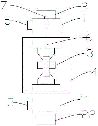
[0033] The technical scheme in the embodiment of the present invention is described below in conjunction with accompanying drawing:

[0034] Reference attached figure 1 , a spark plasma sintering system, including a sintering furnace and a control system connected thereto, the control system includes a pressure / displacement control system, an atmosphere control system, a vacuum control system and a temperature control system; the sintering furnace includes a pressurized device and a pulse current generator, the pressurizing device includes a corresponding upper indenter 1 and a lower indenter 11, an upper electrode 2 and a lower electrode 22 respectively arranged on the upper and lower sides of the upper indenter 1 and the lower indenter 11 , the sintering mold 3 arranged between the upper pressing head 1 and the lower pressing head 11, and the water-cooled vacuum chamber 4 arranged outside the sintering mold 3, the pulse current generator is connected with the upper electrode...


PUM


Abstract

The invention discloses a spark plasma sintering system which comprises a sintering furnace and a control system connected with the sintering furnace. The control system comprises a displacement/pressure control system, an atmosphere control system, a vacuum control system and a temperature control system. The sintering furnace comprises a pressurization device and an impulse current generator. The pressurization device comprises an upper pressing head and a lower pressing head which are correspondingly arranged, upper electrodes and lower electrodes which are arranged on the upper sides and the lower sides of both the upper pressing head and the lower pressing head respectively, a sintering die arranged between the upper pressing head and the lower pressing head and a water cooling vacuum chamber arranged on the outer side of the sintering die, and the impulse current generator is connected with the upper electrodes and the lower electrodes. The spark plasma sintering system is good in forming effect, the forming process is controlled accurately, and the product quality is greatly improved.

Description

technical field [0001] The invention relates to a discharge plasma sintering system. Background technique [0002] The Spark Plasma Sintering (SPS) process is to put metal powder into a mold made of graphite and other materials, and use the upper and lower die punches and energized electrodes to apply a specific sintering power supply and pressing pressure to the sintering powder. Discharge activation, thermoplastic deformation and cooling are a new powder metallurgy sintering technology for preparing high-performance materials. Spark plasma sintering has the characteristics of sintering in the process of pressure. The plasma generated by pulse current and the pressure in the sintering process It is beneficial to reduce the sintering temperature of the powder. The spark plasma sintering method (SP method) can effectively apply the high heat energy of the high-temperature plasma (discharge plasma) generated instantaneously by the spark discharge to the thermal diffusion And ...

Claims


Application Information

Patent Timeline
Patent Type & Authority Applications(China)
IPC IPC(8): B22F3/14B22F3/105
CPCB22F3/003B22F3/105B22F3/14
Inventor 孙矿徐炜
Owner 浙江晨华科技有限公司
Why Eureka
Try Eureka