
A tangential self-excited vibration assisted dry grinding system and method

A self-excited vibration and dry grinding technology, applied in the field of grinding, can solve the problems of affecting the machining accuracy, reducing the rigidity of the machining system, and high energy consumption, so as to reduce the grinding temperature, avoid grinding burns, and increase the normal stiffness. high effect

Active Publication Date: 2018-01-23
SHANDONG UNIV
View PDF4 Cites 0 Cited by
  • Summary
  • Abstract
  • Description
  • Claims
  • Application Information

AI Technical Summary

Problems solved by technology

[0004] However, this technique requires fixing the workpiece to the ultrasonic vibrating system
The structure of the ultrasonic vibration system is relatively complicated, and the corresponding ultrasonic vibration system needs to be replaced for parts of different quality, which has poor versatility, high manufacturing cost and high energy consumption
For ultra-precision machining machine tools, the structure design is compact and the rigidity of the machine tool system is high. An overly complicated ultrasonic vibration device is inconvenient to install, and it will reduce the rigidity of the machining system and affect the machining accuracy.

Method used


Image

  • A tangential self-excited vibration assisted dry grinding system and method
  • A tangential self-excited vibration assisted dry grinding system and method
  • A tangential self-excited vibration assisted dry grinding system and method

Examples


Embodiment Construction

[0025] The invention will be further described in conjunction with the accompanying drawings.

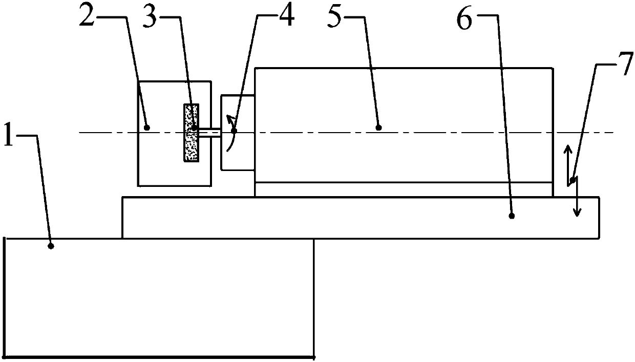
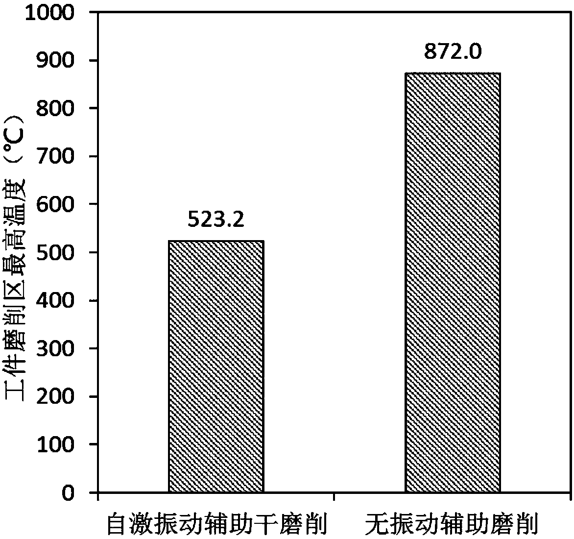
[0026] In order to solve the problem of high grinding temperature and easy burn of the workpiece grinding wheel in dry grinding, a tangential self-excited vibration assisted dry grinding system and method with simple structure, low design and manufacturing cost and convenient operation are proposed. Specifically, the present invention The tangential self-excited vibration assisted dry grinding system includes a grinding head system and a self-excited vibration plate, one end of the self-excited vibration plate is fixed, and the other end is a free end, forming a cantilever beam structure; the grinding head The system is installed on the top of the self-excited vibration plate. The grinding wheel rotation of the grinding head system is used as the excitation source of the grinding system to input energy for the self-excited vibration plate. The self-excited vibration plate drives the ...


PUM


Abstract

The invention discloses a tangential self-excited vibration auxiliary dry grinding system and method. A grinding head system is mounted on a self-excited vibration plate. The self-excited vibration plate is fixed to a machine tool body through a cantilever. During machining, a grinding wheel of the grinding head system rotates to serve as an excitation source of the whole system, energy is input to the self-excited vibration plate, and the self-excited vibration plate drives the grinding head system to subjected to self-excited vibration, so that abrasive grains of the grinding wheel are made to make reciprocating componential movement at a certain frequency in the tangential direction of the grinding wheel relative to a workpiece while grinding the workpiece. By controlling the rotating speed of the grinding wheel, the quantity of input self-excited vibration energy can be adjusted; by analyzing and designing the inherent frequency and modal of the self-excited vibration plate, the frequency of a self-excited vibration system can be controlled; and the abrasive grains of the grinding wheel make contact with or are separated from the workpiece periodically, so that grinding heat is effectively dissipated, and the purposes of decreasing the grinding temperature and avoiding grinding burns are achieved.

Description

technical field [0001] The invention relates to a grinding processing method, which uses the self-excited vibration of a processing system to reduce the grinding temperature in the dry grinding process, avoids grinding burns of workpieces, and reduces grinding wheel wear. Background technique [0002] Grinding is a precision machining method that takes into account both efficiency and quality, but it has the disadvantages of high grinding force, high grinding temperature, and easy burns of workpieces and grinding wheels. In general grinding, it is necessary to pour a large amount of coolant to cool and lubricate the grinding area, so as to reduce the grinding temperature and reduce the grinding force, so as to avoid grinding burns. Grinding fluids mostly contain chemical additives, and the large amount of use, especially the later discharge treatment, cannot avoid certain pollution to the environment. Moreover, for some special materials (such as quartz glass, KDP crystal, ...

Claims


Application Information

Patent Timeline
Patent Type & Authority Patents(China)
IPC IPC(8): B24B1/04B24B55/02
CPCB24B1/04B24B55/02
Inventor 姚鹏王伟黄传真王军刘含莲朱洪涛邹斌
Owner SHANDONG UNIV
Learn More