
Multidimensional variable parameter vibration mechanical polishing device and fuzzy PID control method thereof

A technology of mechanical polishing and variable parameters, which is applied in the direction of electric controllers, grinding/polishing equipment, controllers with specific characteristics, etc., and can solve problems such as low processing efficiency and manufacturing precision, inability to adjust vibration frequency, and limited scope of application. , to achieve the effect of uniformity removal, elimination of kinematic coupling, and improvement of processing quality

Inactive Publication Date: 2016-12-21
TIANJIN UNIVERSITY OF TECHNOLOGY
View PDF6 Cites 6 Cited by
  • Summary
  • Abstract
  • Description
  • Claims
  • Application Information

AI Technical Summary

Problems solved by technology

For example, after diamond cutting, knife marks will be produced, which will affect the optical performance; grinding process will easily break and damage the sharp part of the microstructure; EDM and laser processing have low processing efficiency and manufacturing accuracy, and the scope of application is limited, which requires further improvement. The level of manufacturing technology for the mold surfaces used to produce such optics
[0003] Studies have shown that for the production of mold surfaces for complex optical elements and microstructured optical elements, the use of vibration mechanical polishing can significantly improve the processing quality and efficiency, but there are still many shortcomings in the current vibration polishing: (1) The vibration form is one-dimensional vibration polishing Or two-dimensional vibration polishing, wherein the vibration trajectory of one-dimensional vibration polishing is parallel to the processed surface or perpendicular to the processed surface, and two-dimensional vibration polishing is a polishing tool that makes a certain trajectory in the tangent plane or orthogonal normal plane of the processed surface , such as circular, elliptical, or Lissajous trajectories
(2) Existing vibration devices, no matter one-dimensional vibration polishing device or two-dimensional vibration polishing device, are designed based on the principle of resonance. Although the vibration frequency is high, the vibration frequency cannot be adjusted according to actual needs
At present, there is no three-dimensional non-resonant mechanical polishing device applied to polishing processing. The present invention provides a multi-dimensional variable parameter vibration polishing device, which can make the polishing tool obtain the desired two-dimensional and three-dimensional variable parameter vibration trajectory according to the needs. Complex mold Ultra-precision mechanical polishing of curved and microstructured surfaces

Method used


Image

  • Multidimensional variable parameter vibration mechanical polishing device and fuzzy PID control method thereof
  • Multidimensional variable parameter vibration mechanical polishing device and fuzzy PID control method thereof
  • Multidimensional variable parameter vibration mechanical polishing device and fuzzy PID control method thereof

Examples


Embodiment 1

[0124] According to the actual motion trajectory of the polishing head and the actual processing surface roughness requirements, determine the required three-dimensional vibration parameters: including the size of the major and minor axes of the ellipse, the orientation of the ellipse plane, the frequency of the ellipse motion, etc., according to the formula (1)- (3) Generate ideal displacements of the motion track in the X-axis, Y-axis and Z-axis directions, and output drive voltage signals in the X-axis, Y-axis and Z-axis directions.

[0125] Apply u to the X-axis piezoelectric stack, Y-axis piezoelectric stack and Z-axis piezoelectric stack respectively x (t), u y (t), u z (t) drive signal, Figure 6-9 Its three-dimensional, xoy, xoz and yoz plane motion trajectories are shown respectively.

[0126] u x (t)=30sin(wt+π / 6) (22)

[0127] u y (t)=50sin(wt+5π / 6) (23)

[0128] u z (t)=60sin(wt+2π / 6) (24)

[0129] The displacement sensor measures the actual displacement o...


PUM


Abstract

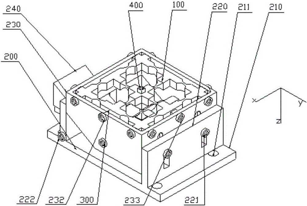
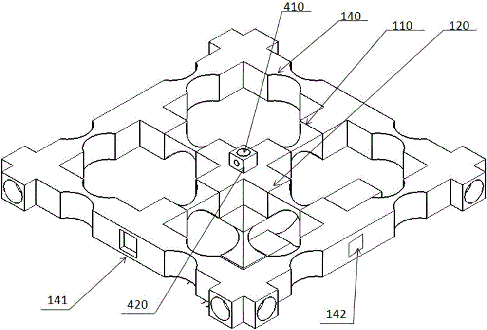
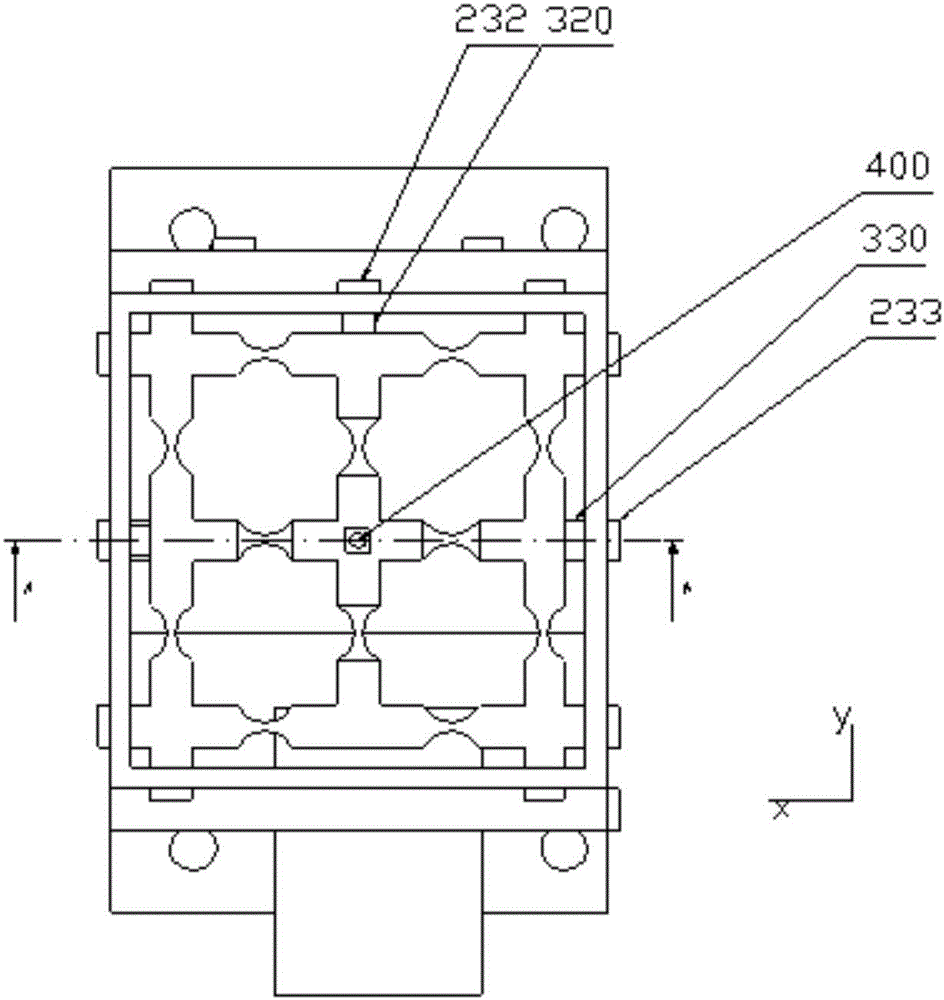
The invention discloses a multidimensional variable parameter vibration mechanical polishing device comprising a cross structure formed by connecting a x axis hinge and a y axis hinge; the center of the cross structure is connected with a polishing head; the polishing head is connected with one end of a z axis hinge; the other end of the axis hinge is provided with a first counterbore; a square structure is formed by interconnection of unidirectional hinges and a structure shaped like a Chinese character 'tian' is formed by connecting the square structure and the cross structure; a second counterbore and a third counterbore are respectively opened at the centers of two adjacent sides of the square structure; a z axis drive unit is connected with the first counterbore and is used for driving the z axis bidirectional hinge to move in the direction of the z axis; a y axis drive unit is connected with the second counterbore and is used for driving the square structure to move in the direction of the y axis; an x axis drive unit is connected with the third counterbore and is used for driving the structure shaped like a Chinese character 'tian' to move in the direction of the x axis. The polishing device of the invention adopts symmetrical uniaxial and biaxial flexible hinge structure so that the polishing grinding head realizes a certain locus movement in three-dimensional space and can eliminate the motion coupling.

Description

technical field [0001] The present invention relates to a vibrating mechanical polishing device. More specifically, the present invention relates to a multidimensional variable parameter vibration mechanical polishing device and a fuzzy PID control method thereof. Background technique [0002] Complex optical components and micro-structured optical components are more and more widely used in many important fields such as national defense and aerospace, which put forward higher requirements and challenges for the mold polishing technology used to produce such optical components. In order to improve the processing quality and efficiency, a variety of processing methods have been used to produce the mold surface processing of such optical components, such as diamond precision turning, ultra-precision grinding, EDM and laser processing. But the effect is not ideal. For example, after diamond cutting, knife marks will be produced, which will affect the optical performance; grin...

Claims


Application Information

Patent Timeline
Patent Type & Authority Applications(China)
IPC IPC(8): B24B1/04B24B41/02B24B41/00G05B11/42
CPCB24B1/04B24B41/00B24B41/02G05B11/42
Inventor 王桂莲周晓勤马培群朱培浩刘婕周海波乔志峰
Owner TIANJIN UNIVERSITY OF TECHNOLOGY
Learn More