Long-effectiveness passive containment cooling system

A passive containment and cooling system technology, applied in the field of nuclear power, can solve the problems of loss of AC power supply inside and outside the plant, lack of timeliness, rupture of containment, etc., to eliminate hidden dangers of structural strength and stability, and improve resistance to extreme events capability, enhanced safety and reliability effects

Active Publication Date: 2016-12-21
CHINA NUCLEAR POWER TECH RES INST CO LTD +2
View PDF6 Cites 8 Cited by
  • Summary
  • Abstract
  • Description
  • Claims
  • Application Information

AI Technical Summary

Problems solved by technology

In the normal operation of the nuclear power plant, the recirculation loop maintains the normal state of the water tank; in the event of an accident, the recirculation loop is a non-safety system. If the nuclear power plant is located in a low temperature zone, the water in the water tank may freeze. The water in the sprinkler pipes may freeze, preventing an effective safety shower
[0005] 2. In the passive way of spraying and cooling the outer wall of the steel containment by relying on the low-temperature water in the passive containment cooling water tank (PCCWST) after the accident of the existing nuclear power plant, the water volume in the water tank is only sufficient for a short time (such as : 72 hours, the containment structure is not enough to bear a larger load) functional requirements
In the case of extreme natural disasters, such as the Fukushima nuclear accident, the AC power supply inside and outside the plant is completely lost for a long time. When the water tank of PCCWST is emptied, there is no power source to drive the recirculation pump to replenish water
If only relying on air convection to cool the outer wall of the containment is not enough to discharge the waste heat in the reactor, the high pressure inside the conta

Method used


Image

  • Long-effectiveness passive containment cooling system
  • Long-effectiveness passive containment cooling system
  • Long-effectiveness passive containment cooling system

Examples


Embodiment Construction

[0028] The technical solutions in the embodiments of the present invention are clearly and completely described. Obviously, the described embodiments are only some embodiments of the present invention, not all embodiments. Based on the embodiments of the present invention, all other embodiments obtained by persons of ordinary skill in the art without creative efforts fall within the protection scope of the present invention.

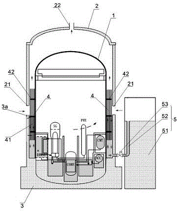
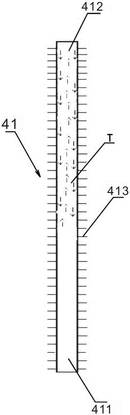
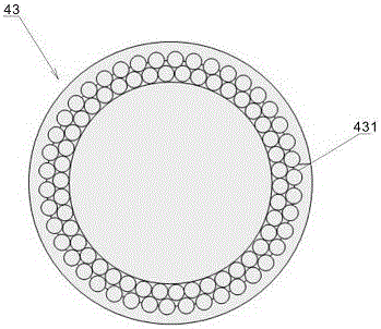
[0029] see in conjunction Figure 1-Figure 3 , is Embodiment 1 of the long-term passive containment cooling system of the present invention.

[0030] The long-term passive containment cooling system in this embodiment includes: a steel containment vessel 1; a concrete shielding layer 2 arranged outside the steel containment vessel 1; The heat exchange pool 3 that can provide static pressure for the containment; the heat exchange tube assembly 4 floating on the liquid surface 3a of the heat exchange pool 3; Enter the air inlet 21 between the steel conta...


PUM

PropertyMeasurementUnit
Boiling pointaaaaaaaaaa

Abstract

The invention discloses a long-effectiveness passive containment cooling system. The heat of water in a heat exchange pool can be transmitted into air between a containment and a concrete shielding layer through evaporation of the water in the heat exchange pool and/or heat exchange of a heat exchange pipe component, the heat can be taken away by air convection between an air inlet and an air outlet, and a water-supplementing device of a containment water-supplementing pool can maintain that the liquid level of the heat exchange pool is basically not changed. By implementation of the long-effectiveness passive containment cooling system provided by the invention, the hidden danger of the containment structural strength and stability can be eliminated, the capacity of the containment water-supplementing pool is increased and the extreme event-resisting ability of the containment is improved; heat exchange power is obviously increased and safe reliability is improved; and temperature reduction and pressure reduction of the containment are effectively realized, so that the integrity of the containment is guaranteed.

Description

technical field [0001] The invention relates to the field of nuclear power, in particular to a long-term passive containment cooling system (PCCS). Background technique [0002] Due to the unreasonable structural design of the passive containment cooling system of the existing nuclear power plant, there are mainly the following technical problems: [0003] 1. The structure carrying a huge water storage tank on the top of the containment can easily lead to structural damage and loss of safety functions in extreme events such as strong earthquakes, sea waves, and tornadoes. [0004] In addition, in this method, the cooling water source is located in the water storage tank above the containment, and the water tank is equipped with redundant liquid level measurement channels and alarms to monitor the water level of the water tank, while redundant temperature measurement channels are provided to monitor temperature and Alarm at low temperature to prevent water from freezing. To...

Claims


Application Information

Patent Timeline
IPC IPC(8): G21C15/18
CPCG21C15/18Y02E30/30
Inventor 杨江卢向晖王婷林支康方思远梁活吕逸君黄熙梁任沈永刚蒋晓华
Owner CHINA NUCLEAR POWER TECH RES INST CO LTD
Why Eureka
Try Eureka