Stirring type wet flue gas desulfurization device of sintering machine

A desulfurization device and stirring technology, which is applied in the field of agitating wet flue gas desulfurization devices of sintering machines, can solve the problems of insufficient oxidation of sulfite, incomplete desulfurization, low desulfurization efficiency, etc., so as to increase the effect and the desulfurization time. , saving manpower and material resources, high desulfurization efficiency

Inactive Publication Date: 2017-01-04
HEFEI HEYI ENVIRONMENTAL PROTECTION TECH ENG
View PDF5 Cites 9 Cited by
  • Summary
  • Abstract
  • Description
  • Claims
  • Application Information

AI Technical Summary

Problems solved by technology

[0007] In order to overcome the shortcomings of insufficient oxidation of sulfite generated by desulfurization, low desulfurization efficiency, and incomplete desulfurization, the technical problem to be solved by the present i

Method used


Image

  • Stirring type wet flue gas desulfurization device of sintering machine
  • Stirring type wet flue gas desulfurization device of sintering machine
  • Stirring type wet flue gas desulfurization device of sintering machine

Examples


Embodiment 1

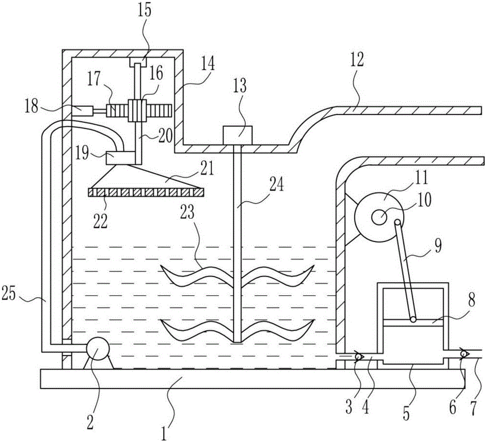
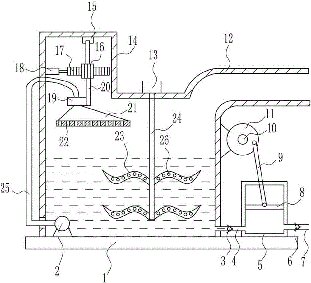
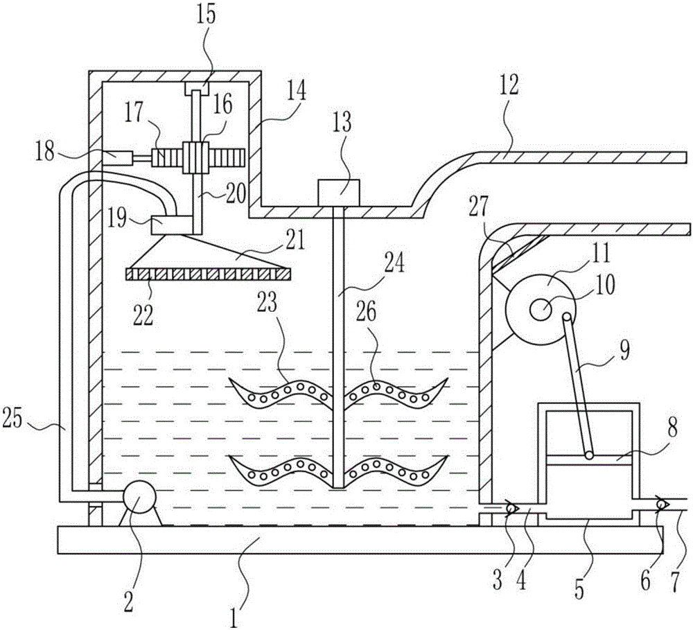
[0035] A sintering machine stirring wet exhaust gas desulfurization device, such as Figure 1-4As shown, it includes a bottom plate 1, a water pump 2, a first one-way valve 3, a hard pipe 4, a compression cylinder 5, a second one-way valve 6, an intake pipe 7, a piston 8, a connecting rod 9, a first motor 10, Disc 11, smoke exhaust pipe 12, second motor 13, processing box 14, bearing housing 15, gear 16, rack 17, electric push rod 18, fixed sleeve 19, rotating rod 20, nozzle 21, stirring blade 23, stirring Rod 24 and flexible pipe 25, base plate 1 is provided with treatment box 14 and compression cylinder 5, treatment box 14 is positioned at the left side of compression cylinder 5, is connected with hard Pipe 4, hard pipe 4 is provided with a first one-way valve 3, the lower part of the right side of the compression cylinder 5 is provided with an air intake pipe 7, the air intake pipe 7 is provided with a second one-way valve 6, and the compression cylinder 5 is provided with ...

Embodiment 2

[0037] A sintering machine stirring wet exhaust gas desulfurization device, such as Figure 1-4 As shown, it includes a bottom plate 1, a water pump 2, a first one-way valve 3, a hard pipe 4, a compression cylinder 5, a second one-way valve 6, an intake pipe 7, a piston 8, a connecting rod 9, a first motor 10, Disc 11, smoke exhaust pipe 12, second motor 13, processing box 14, bearing housing 15, gear 16, rack 17, electric push rod 18, fixed sleeve 19, rotating rod 20, nozzle 21, stirring blade 23, stirring Rod 24 and flexible pipe 25, base plate 1 is provided with treatment box 14 and compression cylinder 5, treatment box 14 is positioned at the left side of compression cylinder 5, is connected with hard Pipe 4, hard pipe 4 is provided with a first one-way valve 3, the lower part of the right side of the compression cylinder 5 is provided with an air intake pipe 7, the air intake pipe 7 is provided with a second one-way valve 6, and the compression cylinder 5 is provided with...


PUM

PropertyMeasurementUnit
Diameteraaaaaaaaaa
Lengthaaaaaaaaaa
Widthaaaaaaaaaa

Abstract

The invention relates to a wet flue gas desulfurization device, in particular to a stirring type wet flue gas desulfurization device of a sintering machine. The stirring type wet flue gas desulfurization device of the sintering machine can fully oxidize sulfite generated by desulfurization, is high in desulfurization efficiency and can achieve complete desulfurization. In order to solve technical problems, the stirring type wet flue gas desulfurization device of the sintering machine comprises a bottom plate, a water pump, a first one-way valve, a hard pipe, a compression cylinder, a second one-way valve, a gas inlet pipe, a piston, a connection rod, a first motor, a disc, a flue gas exhaust pipe and the like. A treatment box and the compression cylinder are arranged on the bottom plate, and the treatment box is located on the left of the compression cylinder. A desulfurization agent makes full contact with oxygen in air for oxidation, then discharged flue gas is subjected to desulfurization, and meanwhile the desulfurization agent circulates by means of the water pump.

Description

technical field [0001] The invention relates to a wet exhaust gas desulfurization device, in particular to a sintering machine stirring wet exhaust gas desulfurization device. Background technique [0002] The sintering machine is suitable for the sintering operation of large-scale ferrous metallurgical sintering plants, and is mainly suitable for the sintering treatment of iron ore powder in large and medium-sized sintering plants. [0003] Wet desulfurization is characterized by the fact that the desulfurization system is located at the end of the flue and after the dust collector. The reaction temperature of the desulfurization process is lower than the dew point, so the desulfurized flue gas needs to be reheated before it can be discharged. Because it is a gas-liquid reaction, the desulfurization reaction speed is fast, the efficiency is high, and the utilization rate of desulfurization additives is high. For example, when lime is used as a desulfurizer, when Ca / S=1, the...

Claims


Application Information

Patent Timeline
IPC IPC(8): B01D53/78B01D53/50B01J19/18B01J4/00
CPCB01D53/78B01D53/501B01D53/502B01D2251/404B01D2251/606B01D2258/0283B01J4/002B01J19/18
Inventor 汪为忠
Owner HEFEI HEYI ENVIRONMENTAL PROTECTION TECH ENG
Why Eureka
Try Eureka