Tool provided with cutting chip flow guiding capillaries and functions and machining method of tool

A capillary and tool technology, which is applied to tools for lathes, cutting inserts, metal processing equipment, etc., can solve the problems of cooling and lubricating fluid infiltration, cluttered capillaries, and poor control of width and depth, reducing cutting force and Effects of cutting heat, extended tool life, and improved workpiece quality

Inactive Publication Date: 2017-01-04
JIANGSU UNIV
View PDF8 Cites 14 Cited by
  • Summary
  • Abstract
  • Description
  • Claims
  • Application Information

AI Technical Summary

Problems solved by technology

The formation of the above-mentioned "capillary" is caused by the rough contact surface of the tool. The formed "capillary" is messy, its width and depth cannot be well controlled, and the cooling lubricant cannot penetrate into the knife-chip bonding area and slide to the maximum extent. area or near the cutting edge, forming a lubricant film

Method used


Image

  • Tool provided with cutting chip flow guiding capillaries and functions and machining method of tool
  • Tool provided with cutting chip flow guiding capillaries and functions and machining method of tool

Examples


Embodiment 1

[0024] In this embodiment, the cutting tool is made of high-speed steel, the cutting material is aluminum alloy, and the cutting method is pouring.

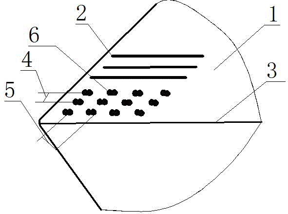
[0025] In this embodiment, the diode-pumped YAG laser is the first choice. By laser processing the working surface of the high-speed steel tool material, the pouring cutting method is adopted. Since the feed rate of the pouring cutting method is relatively large, it is necessary to actively form a wider and deeper hole at the bottom of the chip. Capillary: Due to the cutting of soft aluminum alloy material, the size of the texture array can be completely copied to the bottom of the chip to form the best capillary.

[0026] The implementation of technical characterictic of the present invention comprises the following steps:

[0027] In step A, the surface of the tool is pretreated; the surface of the tool to be textured is polished so that the measured surface roughness Ra is less than 0.3 microns.

[0028] Step B: Carry out las...

Embodiment 2

[0036] In this embodiment, the cutter is a PCBN cutter, the cutting material is hard titanium alloy, and the cutting method is spraying.

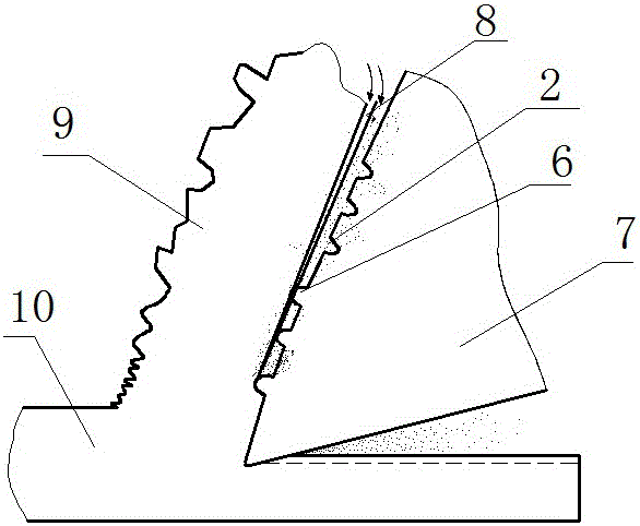
[0037] Fiber laser is the first choice in this embodiment. By laser processing the working surface of PCBN tool material, due to the cutting of hard titanium alloy material, the size of the texture array cannot be completely copied at the bottom of the chips. It is necessary to control the arrangement and size of the texture array so that at the bottom of the chips Optimal capillary formation.

[0038] The implementation of technical characterictic of the present invention comprises the following steps:

[0039] In step A, the surface of the tool is pretreated; the surface of the tool to be textured is polished so that the measured surface roughness Ra is less than 0.3 microns.

[0040] Step B, laser processing is carried out on the working surface of the PCBN tool, and the asperity shape array is processed, which is 200 microns away from ...


PUM

PropertyMeasurementUnit
heightaaaaaaaaaa
diameteraaaaaaaaaa
widthaaaaaaaaaa

Abstract

The invention discloses a tool provided with cutting chip flow guiding capillaries and functions and a machining method of the tool, relates to the tool in which the flow guiding capillaries are formed initiatively at the bottoms of cutting chips, and belongs to the field of mechanical manufacturing. The tool is characterized in that a texture array is arranged on the surface (1), on one side of the flowing direction of the cutting chips, of the tool; the texture array is formed by combination of micro-bulge (6) arrays and micro-groove (2) arrays; and the micro-bulge (6) arrays and the micro-groove (2) arrays are sequentially arranged along the flowing direction of the cutting chips. According to the tool, when a wet cutting machining mode is adopted, the direction of pouring or spraying is aligned with the direction of the capillaries or micro-grooves. Friction between the tool and the cutting chips is reduced; and cutting fluid reaches a bonding zone and a sliding zone, so that cutting force and cutting heat are lowered, and the service life of the tool is prolonged.

Description

technical field [0001] The invention relates to a tool for actively forming a diversion capillary at the bottom of chips, its application and processing method, and belongs to the field of mechanical manufacturing. Background technique [0002] During metal cutting, the chip and the rake face produce severe friction, and the cutting heat accumulates near the tool tip, resulting in a sharp rise in the local temperature of the tool. The edge strength is reduced, resulting in edge chipping; at the same time, during the cutting process of highly plastic metal materials, "sticking knife" forms built-up edge, which affects the surface quality and dimensional accuracy of the workpiece. Therefore, tool surface wear and adhesion are related to cutting quality and tool life. [0003] In 1958, Merchant et al. (The physical chemistry of cutting fluid action) discovered with a microscope that there was a capillary with a diameter of about 0.2mm in the knife-chip contact area, which prov...

Claims


Application Information

Patent Timeline
Patent Type & Authority Applications(China)
IPC IPC(8): B23B27/00B23P15/30
CPCB23B27/00B23B2200/081B23B2200/086B23P15/30
Inventor 符永宏邹国文康正阳郑峰王浩华希俊纪敬虎符昊
Owner JIANGSU UNIV
Why Eureka
Try Eureka