Improved structure of air bearing

A technology of air bearing and structure, which is applied in the direction of bearings, shafts and bearings, mechanical equipment, etc., can solve the problems of heat loss, bearing deformation, high cost, etc., and achieve the effect of improving stability

Inactive Publication Date: 2017-01-04
HIWIN MIKROSYST
View PDF7 Cites 4 Cited by
  • Summary
  • Abstract
  • Description
  • Claims
  • Application Information

AI Technical Summary

Problems solved by technology

[0003] In precision processing machinery or measuring instruments that require high positioning accuracy and fast movement, traditional liquid bearings are prone to deformation and heat loss due to high speed and temperature rise effects, resulting in damage to liquid bearings. Under the circumstances, the air bearing of the air static pressure type is particularly suitable for high-speed movement because the viscosity of the gas is much lower than the liquid viscosity of the traditional liquid bearing. The ability and rigidity are also relatively low, which limits the scope of its specific application
[0004] The air bearing of the air static pressure type uses the air supply system to supply pressurized gas into the restrictor, and then introduces the gas into the bearing gap through the restrictor to generate static pressure to carry the load, and through the structure of different throttling air, Air bearings can be made with different characteristics, among them, the restrictor made of air-permeable porous material has better stability and load capacity than other known restrictors, but due to its manufacturing It is relatively difficult, resulting in its high cost, and it is difficult to be widely used. At the same time, it is difficult to control the internal pores of the porous material, which makes it difficult to obtain better adjustment and control of pore size and distribution state. The setting status of

Method used


Image

  • Improved structure of air bearing
  • Improved structure of air bearing
  • Improved structure of air bearing

Examples


Embodiment Construction

[0022] That is to say, a preferred embodiment of the present invention will be given together with the drawings for further description.

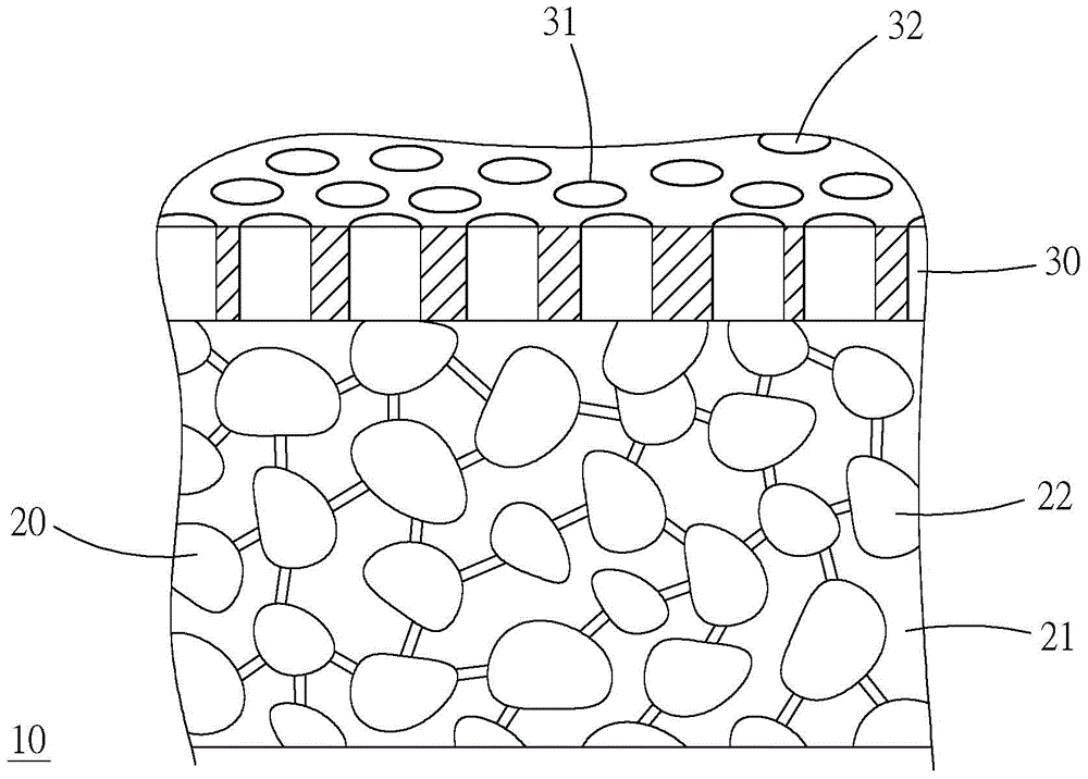
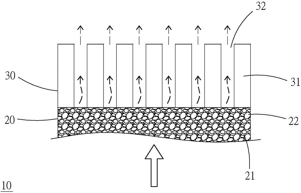
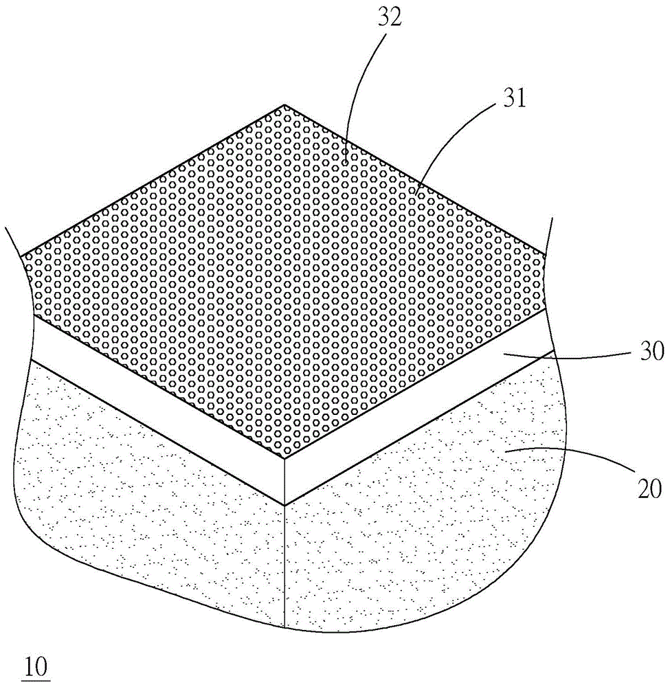
[0023] see Figure 1 to Figure 4 As shown, the air bearing improved structure 10 provided in the first preferred embodiment of the present invention mainly includes a porous body 20 and a throttle layer portion 30, wherein:

[0024] The porous body 20 is made by a known sintering technique, and has a base 21, an air chamber 22 located inside the base 21 and formed by a plurality of voids communicating with each other, and the plurality of voids constitute a gas flow path , so as to obtain the effect similar to that of the known porous restrictor.

[0025] The throttling layer portion 30 is composed of an aluminum layer 31 and a plurality of through holes 32 with a predetermined length, and is arranged on one end surface of the porous body 20. Further, the aluminum layer 31 is deposited by physical vapor deposition ( Physical Vapor Deposit...


PUM


Abstract

The invention provides an improved structure of an air bearing, and the improved structure is a porous air bearing which comprises a porous body and a throttling layer part; the porous body is provided with a base part and an air chamber arranged on the base part, and is formed by enabling a plurality of gaps inside the base part to communicate with one another; the throttling layer part is arranged on one side end surface of the porous body, and is composed of an aluminum layer and a plurality of through holes with predetermined length; the through holes separately penetrate through the aluminum layer in the same direction relative to each other, and communicate with the air chamber. In order to increase, degree of freedom of regulation, on hole diameter parameters, of a porous material, double-layer limitation of the porous material, the through hole aluminum layer and the like is matched with through holes which are distributed in equal rectangular array and nano-scale hole diameters, so that hole uniformity, permeability consistency and isotropy are guaranteed; and meanwhile, bearing force, gas film stability and static rigidity are increased.

Description

technical field [0001] The present invention is related to gas bearing technology, in particular to an improved structure of static pressure air bearing with high aspect ratio aperture. Background technique [0002] Air bearings, sliding bearings with gas as lubricant, increase the gas pressure in the gap between two relative displacement objects through the viscosity of the gas, so as to float the objects and carry the load. Its low friction coefficient and low friction torque characteristics are suitable for In the technical field of high-speed motion, the gas film formed between the relative displacement end faces can reduce the vibration amplitude during motion, and can meet the needs of high motion precision. In addition, the air bearing has more advantages such as service life Long, easy to maintain, not susceptible to temperature and other characteristics, making air bearings widely used in many different industries. [0003] In precision processing machinery or meas...

Claims


Application Information

Patent Timeline
Patent Type & Authority Applications(China)
IPC IPC(8): F16C32/06
Inventor 林耘纬颜堉安何长政
Owner HIWIN MIKROSYST
Why Eureka
Try Eureka