Eureka AIR delivers breakthrough ideas for toughest innovation challenges, trusted by R&D personnel around the world.

Residual stress measurement system through hole-drilling method

A measuring system and residual stress technology, applied in the direction of measuring force, measuring device, instrument, etc., can solve the problems such as the influence of drilling operation and drilling strain value, insufficient flexibility and convenience, and insufficient calculation system. The effect of shortened test cycle, improved adaptability and accuracy, and improved test success rate

Inactive Publication Date: 2017-01-04
INST OF METAL RESEARCH - CHINESE ACAD OF SCI
View PDF9 Cites 10 Cited by
  • Summary
  • Abstract
  • Description
  • Claims
  • Application Information

AI Technical Summary

Problems solved by technology

At present, the common problems of low-speed equipment are: 1) The diameter of the drilling hole is fixed, and it is inconvenient to replace the chuck
2) The drill pipe is directly in contact with the positioning sleeve, which affects the drilling operation and the strain value of the drilling process
3) The calculation system of the system is not perfect, because the processing strain and the plastic deformation of the hole edge change with the stress, the error is large when testing the high stress field 4) The flexibility and convenience of the equipment on site are not enough
Patent 4 (Application No.: 200920105688.4; Invention Name: A Magnetic Full-Surface Drilling Device Using Blind Hole Method for Stress Measurement) mainly discloses a method for quickly fixing the surface of ferromagnetic materials, which has improved the test to a certain extent. The purpose of efficiency, but not suitable for non-ferromagnetic materials such as aluminum alloy

Method used


Image

  • Residual stress measurement system through hole-drilling method
  • Residual stress measurement system through hole-drilling method
  • Residual stress measurement system through hole-drilling method

Examples


Embodiment 1

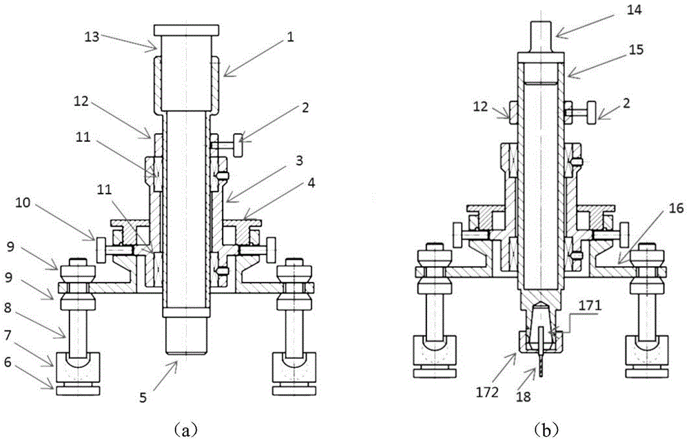
[0035] Adopt above-mentioned content of the present invention, develop such as Figure 4 (a) The KJS-HD-1 type drilling method measuring residual stress system shown in (a), including 30X tool microscope, φ22mm drill pipe, magnetic support base with guide cylinder, 0-3000rpm variable speed hand drill, 3.5″PDA handheld Type stress-strain acquisition and calculation equipment, BE120-2CA-B three-way strain rosette. The front end of the drill pipe is equipped with ER11A-3 CNC special elastic collet, NACHI high-precision variable-diameter hard drill: clamping section φ3mm, cutting tool section φ1. 5mm.

[0036] The measurement system of the present invention pastes three-way strain rosettes on the material to be measured, and the three-way strain rosettes are connected to strain gauges; Figure 4 (b) is the stress calculation interface, and the calculation adopts a two-way formula to facilitate the calculation of welding residual stress, as shown in the following formula (1):

[...


PUM


Abstract

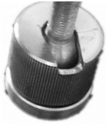
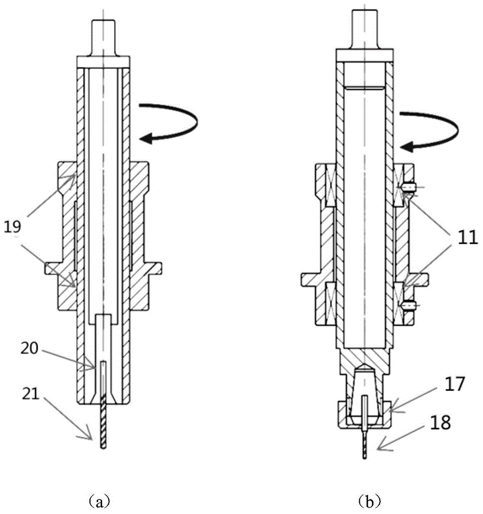
The invention discloses a residual stress measurement system through a hole-drilling method, and belongs to the technical field of material processing and experimental stress analysis. The system comprises two parts: a drilling device and stress calculation software. The drilling device is formed by a speed-adjustable electric hand drill, a tool microscope, a drill rod, a guide cylinder and a magnetic support base and the like; and the calculation software is programmed through C language, and can give residual stress in an assigned direction, or principal stress and included angle in real time. Since a drilling guide device adopts an embedded ball bearing mode, an rotary friction effect of the drill rod is totally prevented; since the support adopts permanent magnetic bases and lock nuts each having a breach, site positioning and fillet weld stress measurement are realized greatly; and since the calculation program takes features of change of hole edge plastic deformation and processing strain with the stress value into consideration, a stress calculation formula of any two vertical directions is given to enable welding residual stress measurement to become much easier and accurate.

Description

technical field [0001] The invention relates to the technical field of material processing and experimental stress analysis, in particular to a drilling method residual stress measurement system. Background technique [0002] Residual stress exists in most of the components manufactured by welding and other thermal processing processes. Higher values ​​of residual stress will have an adverse effect on the long-term safe use of components. Controlling and measuring residual stress has become a very important research and application direction. [0003] In structures such as welding, the method of drilling to measure residual stress has been widely used. The principle of the drilling method to measure the residual stress is to paste a three-way or two-way strain rosette on the measured part of the workpiece, and process a small blind hole of Φ1.5-3mm in the center of the strain rosette to cause the release of the residual stress. The stress- The release strain relationship ca...

Claims


Application Information

Patent Timeline
Patent Type & Authority Applications(China)
IPC IPC(8): G01L1/00
Inventor 陈怀宁黄春玲陈静李东旭
Owner INST OF METAL RESEARCH - CHINESE ACAD OF SCI
Why Eureka
Eureka Blog
Learn More