
Three-dimensional metal printing method integrating machining technology and three-dimensional metal printing equipment

A 3D printing and machining technology, applied in the field of additive manufacturing, can solve the problems of large metal loss, metal layer damage, and low forming precision

Inactive Publication Date: 2017-01-11
NANJING TAITAO INTELLIGENT SYST CO LTD
View PDF10 Cites 7 Cited by
  • Summary
  • Abstract
  • Description
  • Claims
  • Application Information

AI Technical Summary

Problems solved by technology

In view of the shortcomings of the above-mentioned SLM and EBM technologies, there have also been many low-cost metal 3D printing technologies using other forming methods, for example, the application number is 201510789205.7, and the name is "a method and device for direct 3D printing and manufacturing using liquid metal" Chinese patent application, application number 201510679764.2, titled "A Metal 3D Printing Rapid Prototyping Equipment", and application number 201410206527.X, titled "Extrusion Metal Flow 3D Printer" However, these technologies have problems such as low molding accuracy or low interlayer bonding of the printed metal layer
There are also integrations of metal 3D printing and traditional machining technologies, such as a Chinese patent application with application number 201520920569.X titled "A 3D Printing CNC Machine Tool for Metal Parts". The forming accuracy of accumulated molten metal in surfacing welding is low, and the metal loss caused by machining is large, and the welding torch or surfacing welding will cause damage to the metal layer that has been machined before

Method used


Image

  • Three-dimensional metal printing method integrating machining technology and three-dimensional metal printing equipment
  • Three-dimensional metal printing method integrating machining technology and three-dimensional metal printing equipment
  • Three-dimensional metal printing method integrating machining technology and three-dimensional metal printing equipment

Examples


specific Embodiment

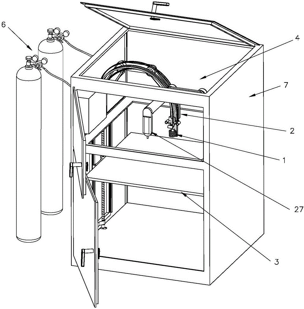
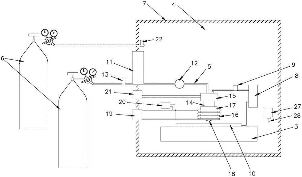
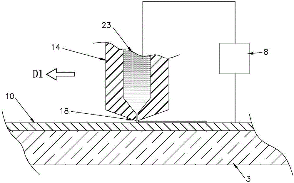
[0094]as attached image 3 to attach Figure 10 A preferred specific embodiment of a metal three-dimensional printing method integrating machining technology shown in the present invention: a metal three-dimensional printing method integrating machining technology, the main process of which is: melting or softening and flowable The metal is placed in the forming area used by the 3D printing equipment (corresponding to the attached figure 1 And attached figure 2 As shown in the molding cavity 4), the melted or softened and flowable metal is transformed into a printed metal after it has no fluidity, and the molten or softened and flowable metal accumulates on the basis of the printed metal until The object to be printed is shaped, and the object to be printed is formed from the accumulated printed and formed metal; wherein: in the process of accumulating the molten or softened and flowable metal, the location where the molten or softened and flowable metal is placed is determ...


PUM


Abstract

The invention discloses a three-dimensional metal printing method integrating a machining technology and three-dimensional metal printing equipment. The three-dimensional metal printing method comprises the core steps of: adopting molten or softened and flowable metal to be contacted with printed metal in a three-dimensional printing process, applying electric current between the molten or softened and flowable metal and the printed metal, rising the temperature of or melting a contact part between the printed metal and the molten or softened and flowable metal by a resistance heating mode to form a metal part with high structural strength, and further machining the printed metal with a cutter. The generated metal part has high density and forming precision; a printing process of each pixel point is monitored; a detachable auxiliary bracket, a printable large part and a damage repairable metal part can be generated synchronously; the equipment is simple in structure and the cost is low. The method and the equipment have a substantial progress.

Description

technical field [0001] The invention relates to three-dimensional printing technology, in particular to a metal three-dimensional printing method and equipment integrating machining technology, and belongs to the technical field of additive manufacturing. Background technique [0002] 3D printing technology first originated in the United States at the end of the 19th century, and was perfected and commercialized in Japan and the United States until the 1970s and 1980s. Common mainstream 3D printing technologies, such as stereolithography (StereoLithography Apparatus, SLA), fused deposition manufacturing (Fused Deposition Modeling, FDM), selective laser sintering (Selecting Laser Sintering, SLS), three-dimensional powder bonding (Three DimensionalPrinting and Gluing, 3DP), was commercialized in the United States in the 1980s and 1990s. The currently commercialized technologies for 3D printing of metal materials mainly include Selective Laser Melting (SLM) and Electron Beam M...

Claims


Application Information

Patent Timeline
IPC IPC(8): B22F3/105B33Y10/00B33Y30/00B33Y50/02
CPCB33Y10/00B33Y30/00B33Y50/02B22F10/00B22F10/32B22F12/70B22F12/10B22F10/22B22F12/20B22F12/22B22F10/30Y02P10/25
Inventor 梁福鹏岳海军罗朝宝
Owner NANJING TAITAO INTELLIGENT SYST CO LTD
Learn More