Self-cleaning cooling structure of Roots vacuum unit

A technology of vacuum unit and Roots vacuum pump, which is applied in the direction of machines/engines, mechanical equipment, liquid fuel engines, etc. It can solve problems such as clogging of rotors and cavities, parking, and reducing the pumping efficiency of vacuum units, and achieve the effect of avoiding clogging

Active Publication Date: 2017-01-11
CHINA ACAD OF AEROSPACE AERODYNAMICS
View PDF7 Cites 2 Cited by
  • Summary
  • Abstract
  • Description
  • Claims
  • Application Information

AI Technical Summary

Problems solved by technology

[0003] At present, the air-cooled Roots vacuum unit has been used in aerospace simulation experiments, and it undertakes the task of gas extraction in the arc heating wind tunnel system. The gas composition in the arc heating wind tunnel is complex, with water vapor, acid gas and various Dust, water vapor and acid gas form an acidic solution, corrode the components of the vacuum system, and form corrosion products. Corrosion products and various dust from the wind tunnel enter the vacuum unit and adhere to the rotor and cavity of the vacuum unit, reducing the vacuum unit. The pumping efficiency will destroy the vacuum of the system, increase the friction force, cause the temperature of the unit to rise and alarm, cause shutdown, and even directly block the rotor and cavity, causing mechanical damage to the vacuum unit

Method used


Image

  • Self-cleaning cooling structure of Roots vacuum unit
  • Self-cleaning cooling structure of Roots vacuum unit
  • Self-cleaning cooling structure of Roots vacuum unit

Examples


Embodiment Construction

[0038] The present invention will be further described in detail below in conjunction with the accompanying drawings, so that those skilled in the art can implement it with reference to the description.

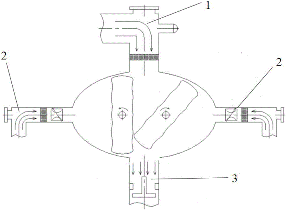
[0039] The invention discloses a Roots vacuum unit self-cleaning and cooling mechanism, such as Figure 1 to Figure 4 As shown, the device includes at least:

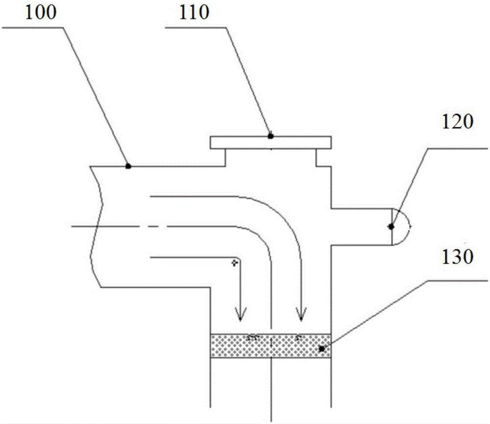
[0040] The impurity removal component 1 is arranged on the intake end of the Roots vacuum pump; the impurity removal component comprises an air intake pipeline 100 which is sealedly connected with the intake end of the Roots vacuum pump, and is arranged in turn on the air intake pipeline An observation window 110, an inflation valve 120 and a first filter 130; the first observation window 110 is used to observe the first filter 130;

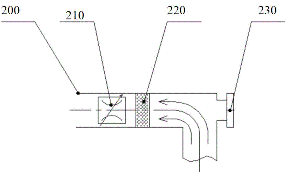
[0041] At least one air supply part 2, which provides cold air to the Roots vacuum pump; the air supply part 2 includes a cold air delivery pipeline 200, and a gas flow regulating valve ...


PUM


Abstract

The invention discloses a self-cleaning cooling structure of a Roots vacuum unit, and the self-cleaning cooling structure is used for solving the internal corrosion problem and the over-temperature parking problem of the Roots vacuum unit. The structure comprises an impurity removal part, a gas supply unit and a gas exhaust pipeline, wherein the impurity removal part is fixedly connected with a gas inlet cavity of a Roots vacuum pump for filtering impurities in working gas; clean air is introduced in a parking process for scouring parts in the pump, so that cleaning and cooling are realized; the gas supply part is fixedly connected with a gas suction cavity of the Roots vacuum pump; during working, clean cold air is introduced into the gas suction cavity for scouring a rotor of the vacuum pump, so that cleaning and cooling are realized; and the gas exhaust pipeline is fixedly connected with a gas exhaust cavity of the Roots vacuum pump for conveying the working gas into a downstream vacuum container, so that gas flow is prevented from returning to the pump cavity during parking. The self-cleaning cooling structure disclosed by the invention can be applied to the vacuum unit for removing complex component gas by sucking, so that damages, on the vacuum unit, of corrosive gas are reduced; and meanwhile, the temperature of the vacuum unit is reduced, and the service life of the vacuum unit is prolonged.

Description

technical field [0001] The invention belongs to the application field of vacuum technology, and in particular relates to a self-cleaning and cooling technology of a Roots vacuum unit for extracting gases with complex components. Background technique [0002] Vacuum technology is widely used in various industries such as aerospace, mechanical electronics, non-ferrous metals, rare earth permanent magnets, and pharmaceutical manufacturing, which has promoted the progress of modern science and technology and the development of industry and agriculture. Roots vacuum unit is widely used as an important vacuum equipment. It has the advantages of high speed and small volume. After realizing air cooling, Roots vacuum unit can work continuously under high pressure without overheating. [0003] At present, the air-cooled Roots vacuum unit has been used in aerospace simulation experiments, and it undertakes the task of gas extraction in the arc heating wind tunnel system. The gas compos...

Claims


Application Information

Patent Timeline
Patent Type & Authority Applications(China)
IPC IPC(8): F04C29/00F04C29/04F04C29/12
CPCF04C29/0092F04C29/042F04C29/12F04C29/124
Inventor 袁国伍陈连忠董永晖苏有为杨汝森陈海群
Owner CHINA ACAD OF AEROSPACE AERODYNAMICS
Why Eureka
Try Eureka