Composite anchor, pipeline connection device using the anchor, and installation method thereof

An anchoring body, anchoring technology, applied in the direction of pipes/pipe joints/pipe fittings, through components, mechanical equipment, etc., can solve the problems of increased manufacturing costs, long installation time, increased production costs, etc., to avoid insufficient tensioning force, improve The effect of improving installation efficiency and production efficiency

Active Publication Date: 2018-07-13
XINXING DUCTILE IRON PIPES CO LTD
View PDF15 Cites 0 Cited by
  • Summary
  • Abstract
  • Description
  • Claims
  • Application Information

AI Technical Summary

Problems solved by technology

The disadvantage of this type of restrictive interface is that the structure is relatively complex and the cost is higher than that of ordinary pipes. The self-anchor ring is usually formed by surfacing welding at the socket end. The construction is inconvenient when the pipeline design is changed, often causing project delays
However, this kind of self-anchoring interface uses steel teeth 26' to embed on the integral annular sealing rubber ring 14'. The manufacturing process of the sealing rubber ring 14' is complicated, and because the hardness is limited by the sealing requirements, the self-anchoring performance is generally not ideal. , can only be used in low pressure state, and cannot meet the application requirements of medium and high pressure, which makes the risk of water leakage at the interface increases sharply when water hammer occurs inside the operating pipeline
Moreover, in the actual installation process, the installer needs to install the entire sealing rubber ring 14' into the corresponding anchor bin 13'. Generally, it needs to bend two to three "several" bends before it can be installed smoothly. At the same time, the steel The existence of the teeth 26' increases the rigidity of the entire sealing rubber ring 14', and it is difficult to adjust the position of the steel teeth 26' during the installation process. It often requires the cooperation of multiple people to complete the installation. The installation takes a long time, the process is complicated, and it is not easy to ensure the installation quality, resulting in artificial waste
In addition, the annular structure of the sealing rubber ring 14' also makes it bulky during transportation and is not easy to stack, resulting in increased transportation costs
In addition, for pipe fittings of different calibers, special molds of corresponding sizes are required to produce rubber rings of different calibers, resulting in increased production costs, more troublesome production organization, and relatively low production efficiency
[0005] In addition, the Chinese invention patent with the publication number CN101044349A also discloses a locking ring, which is a deformation without self-anchor ring structure. It adopts a hardened metal toothed The rigid segment and the connecting element made of elastic material form a locking ring, but because it adopts the connection method of a metal segment and an elastic segment, the size of the metal segment is huge, the processing is difficult, and the manufacturing cost is increased. In actual use, Due to the small size of the elastic element, when the outer diameter of the pipe is at the lower limit of the tolerance, the tension force provided by the elastic element will decrease sharply, and the self-anchoring effect is difficult to achieve, and the surface of the pipe often has a certain curvature, and the metal ring cannot be completely attached to the bearing. On the mouth, so the steel teeth cannot guarantee contact with the pipe body, which will easily lead to the failure of the self-anchor function

Method used


Image

  • Composite anchor, pipeline connection device using the anchor, and installation method thereof
  • Composite anchor, pipeline connection device using the anchor, and installation method thereof
  • Composite anchor, pipeline connection device using the anchor, and installation method thereof

Examples


Embodiment Construction

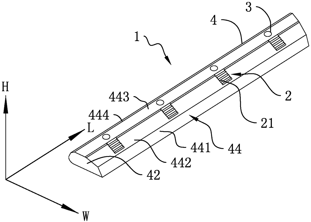
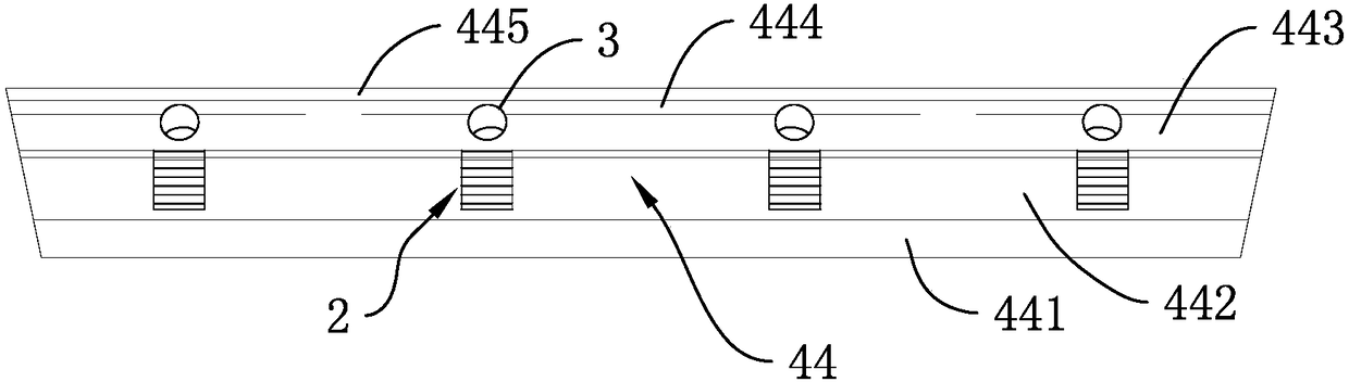
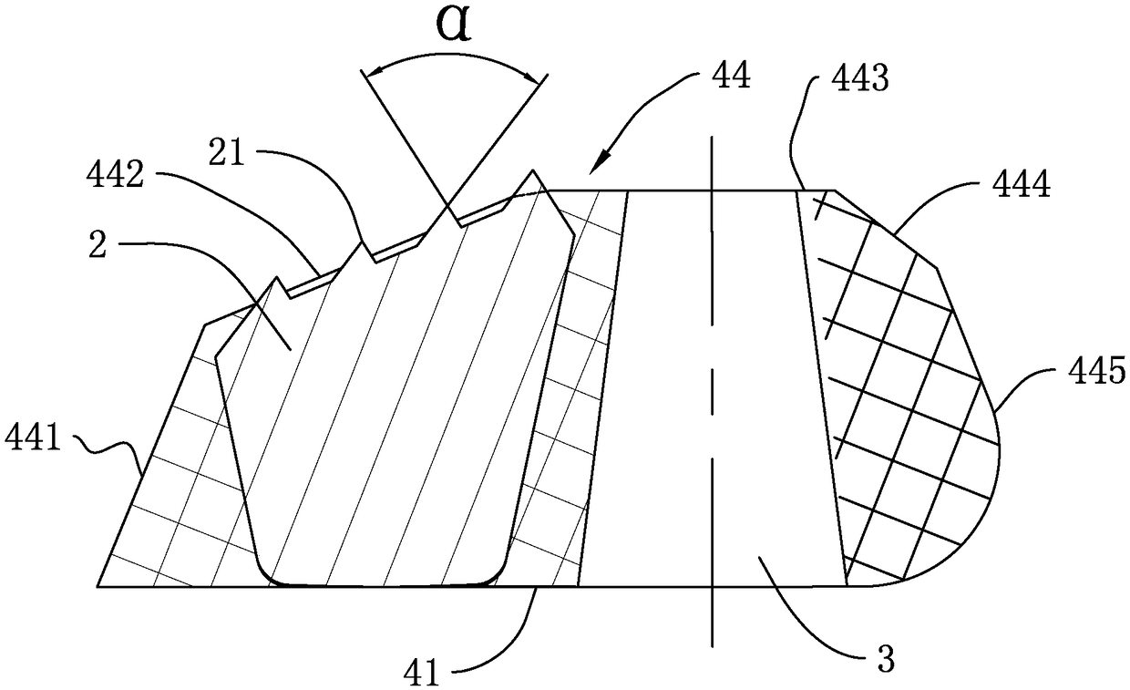
[0033] like Figure 1 to Figure 3As shown, the composite anchor 1 of the present invention includes the elastic body 4. In order to obtain a proper deformation effect, the Shore hardness of the elastic body 4 is 40HA-90HA, preferably 55HA-70HA. The elastic body 4 is a straight polyhedron with a wide bottom and a narrow top. Its bottom surface 41, left end surface 42, and right end surface are all planes, and the top surface 44 is a curved surface formed by zigzags connecting planes and planes. Wherein, the bottom surface 41 is an isosceles trapezoid, and the top surface 44 includes a front connection plane 441 connected with the front edge of the bottom surface 41, a transition plane 442 connected with the front connection plane 441, a horizontal plane 443 connected with the transition plane 442, and a horizontal plane 443 connected with the front edge of the bottom surface 41. Connected transition bevel 444 . The transition slope 444 is connected to the rear edge of the bot...


PUM


Abstract

The invention discloses a combined anchoring body, a pipeline connection device using the same and a mounting method of the pipeline connection device. An elastomer in the combined anchoring body is a wide-end-down straight-strip-shaped polyhedron, the bottom face, the left end face and the right end face of the polyhedron are planes, the bottom face is in an isosceles trapezoid shape, the top face of the polyhedron is a curved surface formed by connecting one plane with another plane in a curved manner, a plurality of racks are inlaid into the elastomer along the length direction at intervals, the tooth crest direction of sawteeth of the racks are parallel to the long sides of the planes which are connected to form the curved surface, the horizontal surface of the elastomer is provided with a plurality of withdrawing portions uniformly distributed along the length direction of the elastomer, and one of the racks is adjacent to at least one of the withdrawing portions along the width direction of the elastomer. After multiple combined anchoring bodies are connected end to end to form an annular anchoring body and the annular anchoring body is placed into an anchoring chamber of a bellmouth of the pipeline connection device, the sawteeth mesh with the outer wall of an insertion opening. The combined anchoring body and the pipeline connection device are simple to produce, convenient to use, good in anchoring effect and adaptive to different diameters of pipes, and the mounting method of the pipeline connection device is simple to operate and high in working efficiency.

Description

technical field [0001] The invention relates to a pipeline interface device, in particular to a composite anchor used for the pipeline interface, a pipeline connection device using the anchor and an installation method thereof. Background technique [0002] In order to stabilize the connection, the traditional pipeline interface needs to be equipped with a self-anchoring structure at the interface. The pipeline interface with the self-anchoring structure has a simple structure and is easy to install. It is widely used in municipal engineering, oil and gas transportation and other fields. [0003] The existing interfaces are mainly divided into two types, one is the structure with self-anchor ring, and the other is the structure without self-anchor ring. The self-anchor ring structure achieves the purpose of self-anchoring of the interface by setting a raised self-anchor ring at the socket and a retaining ring at the socket. A "socket-type pipe joint with anchoring structure...

Claims


Application Information

Patent Timeline
Patent Type & Authority Patents(China)
IPC IPC(8): F16L25/00F16L25/10F16L37/091
CPCF16L25/009F16L25/10F16L37/091
Inventor 李军申勇徐军张涛王嵩左超朱盼车蕾
Owner XINXING DUCTILE IRON PIPES CO LTD
Why Eureka
Try Eureka